Document Outline
- DESCRIPTION
- PINNING
- QUICK REFERENCE DATA
- CIRCUIT DIAGRAM
- LIMITING VALUES
- STIMULATING FIELD STRENGTH
- THERMAL CHARACTERISTICS
- CHARACTERISTICS
- PACKAGE OUTLINE
- DATA SHEET STATUS
- DEFINITIONS
- DISCLAIMERS

DATA SHEET
Product specification
Supersedes data of 2003 Mar 26
2003 Sep 15
DISCRETE SEMICONDUCTORS
KMZ43T
Magnetic field sensor
M3D315

2003 Sep 15
2
Philips Semiconductors
Product specification
Magnetic field sensor
KMZ43T
DESCRIPTION
The KMZ43T is a sensitive magnetic field sensor,
employing the magnetoresistive effect of thin-film
permalloy. The sensor contains two galvanic separated
Wheatstone bridges, at a relative angle of 45
°
to one
another.
A rotating magnetic field in the x-y plane will produce two
independent sinusoidal output signals, one a function of
+cos(2
) and the second a function of +sin(2
),
being
the angle between sensor and field direction (see Fig.3).
Unlike the KMZ41
(1)
, which needs a saturation field
strength of 100 kA/m, the KMZ43T is suited to high
precision angle measurement applications under low field
conditions (saturation field strength 25 kA/m).
The sensor can be operated at any frequency between
DC and 1 MHz.
The information in application notes AN00023
(Contactless Angle Measurement Using KMZ41 and
UZZ9000) and AN00004 (Contactless Angle
Measurement Using KMZ41 and UZZ9001) is applicable
to the KMZ43T, but one should be aware of the difference
in the bridge 1 output.
PINNING
(1) The KMZ41 delivers a +sin(2
) and a
-
cos(2
) signal.
PIN
SYMBOL
DESCRIPTION
1
-
V
O1
output voltage bridge 1
2
-
V
O2
output voltage bridge 2
3
V
CC2
supply voltage bridge 2
4
V
CC1
supply voltage bridge 1
5
+V
O1
output voltage bridge 1
6
+V
O2
output voltage bridge 2
7
GND2
ground 2
8
GND1
ground 1
handbook, halfpage
4
1
5
8
MGD790
pin 1
index
x
y
Fig.1 Simplified outline SOT96-1.
QUICK REFERENCE DATA
SYMBOL
PARAMETER
MIN.
TYP.
MAX.
UNIT
Per bridge
V
CC
supply voltage
-
5
9
V
S
sensitivity (
2
= 0
°
;
1
= 135
°
)
2.1
2.35
2.6
mV/
°
V
offset
offset voltage per supply voltage
-
2
-
+2
mV/V
R
bridge
bridge resistance per bridge
2.7
3.2
3.7
k
2003 Sep 15
3
Philips Semiconductors
Product specification
Magnetic field sensor
KMZ43T
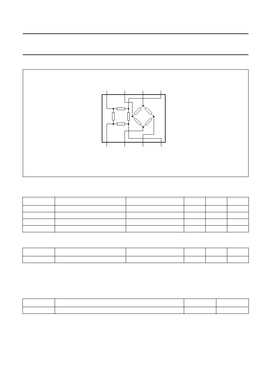
CIRCUIT DIAGRAM
LIMITING VALUES
In accordance with the Absolute Maximum Rating System (IEC 60134).
STIMULATING FIELD STRENGTH
Note
1. The minimum stimulating magnetic field in the x-y plane to ensure minimum angular inaccuracy specified in note 11
to Characteristics table.
THERMAL CHARACTERISTICS
SYMBOL
PARAMETER
CONDITIONS
MIN.
MAX.
UNIT
V
CC1
supply voltage bridge 1
-
9
V
V
CC2
supply voltage bridge 2
-
9
V
T
stg
storage temperature
-
65
+150
°
C
T
amb
operating ambient temperature
-
40
+150
°
C
CONDITIONS
MIN.
CONDITIONS
MIN.
MAX.
UNIT
H
ext
magnetic field strength
note 1
25
-
kA/m
SYMBOL
PARAMETER
VALUE
UNIT
R
th j-a
thermal resistance from junction to ambient
155
K/W
handbook, halfpage
GND1
8
7
6
5
1
2
3
4
MGD789
GND2
+
VO2
+
VO1
-
VO1
-
VO2
VCC2
VCC1
Fig.2 Simplified circuit diagram.

2003 Sep 15
4
Philips Semiconductors
Product specification
Magnetic field sensor
KMZ43T
CHARACTERISTICS
T
amb
= 25
°
C and H
ext
= 25 kA/m; V
CC1
= 5 V; V
CC2
= 5 V; unless otherwise specified.
Notes
1. Sensitivity changes with angle due to sinusoidal output.
2.
where T
1
=
-
40
°
C; T
2
= 150
°
C.
3. V
peak
=
(V
out max
-
V
offset
)
. Periodicity of V
peak
: sin(2
) and cos(2
) respectively.
4.
where T
1
=
-
40
°
C; T
2
= 150
°
C.
5. Bridge resistance between pins 8 and 4, pins 7 and 3, pins 5 and 1, and pins 6 and 2.
6.
where T
1
=
-
40
°
C; T
2
= 150
°
C.
7.
where T
1
=
-
40
°
C; T
2
= 150
°
C.
SYMBOL
PARAMETER
CONDITIONS
MIN.
TYP.
MAX.
UNIT
operating angular velocity
0
-
1
MHz
k
amplitude synchronism
note 9
99.5
100
100.5
%
TC
k
temperature coefficient of
amplitude synchronism
T
amb
=
-
40 to +150
°
C;
note 10
-
0.01
0
-
0.01
%/K
angular inaccuracy
note 11
0
0.05
0.1
deg
Per bridge
V
CC
supply voltage
-
5
9
V
V
offset
offset voltage per supply
voltage
see Fig.3
-
2
0
+2
mV/V
S
sensitivity
open circuit; note 1
1
= 135
°
(bridge 1)
2.1
2.35
2.6
mV/
°
2
= 0
°
(bridge 2)
2.1
2.35
2.6
mV/
°
TC
S
temperature coefficient of
sensitivity
T
amb
=
-
40 to +150
°
C;
note 2
-
0.25
-
0.29
-
0.33
%/K
V
peak
peak output voltage
note 3; see Fig.3
60
67
75
mV
TC
Vpeak
temperature coefficient of
peak output voltage
T
amb
=
-
40 to +150
°
C;
note 4
-
0.25
-
0.29
-
0.33
%/K
R
bridge
bridge resistance
note 5
2.7
3.2
3.7
k
TC
Rbridge
temperature coefficient of
bridge resistance
T
amb
=
-
40 to +150
°
C;
note 6
0.28
0.32
0.35
%/K
TC
Voffset
temperature coefficient of
offset voltage
T
amb
=
-
40 to +150
°
C;
note 7; see Fig.3
-
4
0
+4
(
µ
V/V)/K
FH
hysteresis of output voltage
note 8
0
0.05
0.18
%FS
TC
S
100
=
S
T
2
S
T
1
S
T
1
190
°
C
×
---------------------------------
×
TC
Vpeak
100
=
V
peak T
2
( )
V
peak T
1
( )
V
peak T
1
( )
190
°
C
×
------------------------------------------------------
×
TC
Rbridge
100
=
R
bridge T
2
( )
R
bridge T
1
( )
R
bridge T
1
( )
190
°
C
×
-----------------------------------------------------------
×
TC
Voffset
V
offset T
2
( )
V
offset T
1
( )
190
°
C
---------------------------------------------------------
=

2003 Sep 15
5
Philips Semiconductors
Product specification
Magnetic field sensor
KMZ43T
8.
.
.
9.
.
10.
where T
1
=
-
40
°
C; T
2
= 150
°
C.
11.
=
real
-
measured
without offset voltage influences due to deviations from ideal sinusoidal characteristics.
FH
1
100
=
V
O1 67.5
°
(
)
135
°
45
°
V
O1 67.5
°
(
)
45
°
135
°
2
V
peak1
×
-----------------------------------------------------------------------------------------------------------
×
FH
2
100
=
V
O2 22.5
°
(
)
90
°
0
°
V
O2 22.5
°
(
)
0
°
90
°
2
V
peak2
×
-------------------------------------------------------------------------------------------------
×
k
100
=
V
peak1
V
peak2
-----------------
×
TC
k
100
=
k
T
2
k
T
1
k
T
1
190
°
C
×
--------------------------------
×
handbook, full pagewidth
MBL215
-
VO1
-
VO2
VCC2
VCC1
GND1
direction of
magnetic field
= 0
°
GND2
+
VO2
+
VO1
0
Vout
(mV)
Voffset 1
0
90
-
100
-
50
50
100
180
360
270
(deg)
VO2
Vpeak 1
VO1
0
Fig.3 Output signals related to the direction of the magnetic field.