
TLV431, TLV431A, TLV431B
LOW VOLTAGE ADJUSTABLE PRECISION SHUNT REGULATOR
SLVS139R - JULY 1996 - REVISED SEPTEMBER 2005
1
POST OFFICE BOX 655303
·
DALLAS, TEXAS 75265
D
Low-Voltage Operation . . . V
REF
= 1.24 V
D
Adjustable Output Voltage, V
O
= V
REF
to 6 V
D
Reference Voltage Tolerances at 25
5
C
- 0.5% for TLV431B
- 1% for TLV431A
- 1.5% for TLV431
D
Typical Temperature Drift
- 4 mV (0
5
C to 70
5
C)
- 6 mV (40
5
C to 85
5
C)
- 11 mV (40
5
C to 125
5
C)
D
Low Operational Cathode Current . . .
80
µ
A Typ
D
0.25-
Typical Output Impedance
D
Ultra-Small SC-70 Package Offers 40%
Smaller Footprint Than SOT-23-3
D
See TLVH431 and TLVH432 for
- Wider V
KA
(1.24 V to 18 V) and I
K
(80 mA)
- Additional SOT-89 Package
- Multiple Pinouts for SOT-23-3 and SOT-89
Packages
REF
ANODE
CATHODE
LP (TO-92/TO-226) PACKAGE
(TOP VIEW)
NC - No internal connection
* For TLV431, TLV431A: NC - No internal connection
* For TLV431B: Leave open or connect to ANODE
DBV (SOT-23-5) PACKAGE
(TOP VIEW)
1
2
3
5
4
NC
*
CATHODE
ANODE
REF
DBZ (SOT-23-3) PACKAGE
(TOP VIEW)
1
2
3
REF
CATHODE
ANODE
D (SOIC) PACKAGE
(TOP VIEW)
1
2
3
4
8
7
6
5
REF
ANODE
ANODE
NC
CATHODE
ANODE
ANODE
NC
DCK (SC-70) PACKAGE
(TOP VIEW)
1
2
3
6
5
4
CATHODE
NC
REF
ANODE
NC
NC
NC - No internal connection
r
PK (SOT-89) PACKAGE
(TOP VIEW)
1
3
2
REF
CATHODE
ANODE
ANODE
description/ordering information
The TLV431 is a low-voltage 3-terminal adjustable voltage reference with specified thermal stability over
applicable industrial and commercial temperature ranges. Output voltage can be set to any value between V
REF
(1.24 V) and 6 V with two external resistors (see Figure 2). These devices operate from a lower voltage
(1.24 V) than the widely used TL431 and TL1431 shunt-regulator references.
When used with an optocoupler, the TLV431 is an ideal voltage reference in isolated feedback circuits for 3-V
to 3.3-V switching-mode power supplies. These devices have a typical output impedance of 0.25
. Active
output circuitry provides a very sharp turn-on characteristic, making them excellent replacements for
low-voltage Zener diodes in many applications, including on-board regulation and adjustable power supplies.
Please be aware that an important notice concerning availability, standard warranty, and use in critical applications of
Texas Instruments semiconductor products and disclaimers thereto appears at the end of this data sheet.
Copyright
2005, Texas Instruments Incorporated
PRODUCTION DATA information is current as of publication date.
Products conform to specifications per the terms of Texas Instruments
standard warranty. Production processing does not necessarily include
testing of all parameters.
TLV431, TLV431A, TLV431B
LOW VOLTAGE ADJUSTABLE PRECISION SHUNT REGULATOR
SLVS139R - JULY 1996 - REVISED SEPTEMBER 2005
2
POST OFFICE BOX 655303
·
DALLAS, TEXAS 75265
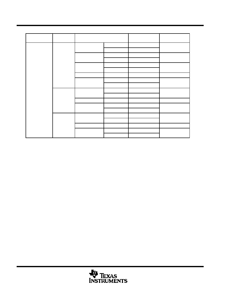
ORDERING INFORMATION
TJ
25
5
C VREF
TOLERANCE
PACKAGE
ORDERABLE
PART NUMBER
TOP-SIDE
MARKING
SC-70 (DCK)
Reel of 3000
TLV431BCDCKR
YE_
SC-70 (DCK)
Reel of 250
TLV431BCDCKT
YE_
SOT-23-5 (DBV)
Reel of 3000
TLV431BCDBVR
Y3GU
SOT-23-5 (DBV)
Reel of 250
TLV431BCDBVT
Y3GU
0.5%
SOT-23-3 (DBZ)
Reel of 3000
TLV431BCDBZR
Y3GU
0.5%
SOT-23-3 (DBZ)
Reel of 250
TLV431BCDBZT
Y3GU
SOT-89 (PK)
Reel of 1000
TLV431BCPK
VE
TO-92 (LP)
Bulk of 1000
TLV431BCLP
TV431B
TO-92 (LP)
Reel of 2000
TLV431BCLPR
TV431B
0
°
C to 70
°
C
SOT-23-5 (DBV)
Reel of 3000
TLV431ACDBVR
VAHC, YAC_§
0 C to 70 C
SOT-23-5 (DBV)
Reel of 250
TLV431ACDBVT
VAHC, YAC_§
1%
SOT-23-3 (DBZ)
Reel of 3000
TLV431ACDBZR
YAC_§
1%
TO-92 (LP)
Bulk of 1000
TLV431ACLP
V431AC
TO-92 (LP)
Reel of 2000
TLV431ACLPR
V431AC
SOT-23-5 (DBV)
Reel of 3000
TLV431CDBVR
VAII, Y3I_§
SOT-23-5 (DBV)
Reel of 250
TLV431CDBVT
VAII, Y3I_§
1.5%
SOT-23-3 (DBZ)
Reel of 3000
TLV431CDBZR
Y3I_§
1.5%
TO-92 (LP)
Bulk of 1000
TLV431CLP
V431C
TO-92 (LP)
Reel of 2000
TLV431CLPR
V431C
Package drawings, standard packing quantities, thermal data, symbolization, and PCB design guidelines are available at
www.ti.com/sc/package.
Possible top-side marking on units prior to August 16, 2004
§ DBV/DBZ/DCK: The actual top-side marking has one additional character that designates the assembly/test site.

TLV431, TLV431A, TLV431B
LOW VOLTAGE ADJUSTABLE PRECISION SHUNT REGULATOR
SLVS139R - JULY 1996 - REVISED SEPTEMBER 2005
3
POST OFFICE BOX 655303
·
DALLAS, TEXAS 75265
ORDERING INFORMATION (continued)
TJ
25
5
C VREF
TOLERANCE
PACKAGE
ORDERABLE
PART NUMBER
TOP-SIDE
MARKING
SC-70 (DCK)
Reel of 3000
TLV431BIDCKR
YF_
SC-70 (DCK)
Reel of 250
TLV431BIDCKT
YF_
SOT-23-5 (DBV)
Reel of 3000
TLV431BIDBVR
Y3FU
0.5%
SOT-23-5 (DBV)
Reel of 250
TLV431BIDBVT
Y3FU
0.5%
SOT-23-3 (DBZ)
Reel of 3000
TLV431BIDBZR
Y3FU
SOT-23-3 (DBZ)
Reel of 250
TLV431BIDBZT
Y3FU
TO-92 (LP)
Bulk of 1000
TLV431BILP
TY431B
TO-92 (LP)
Reel of 2000
TLV431BILPR
TY431B
SOIC (D)
Tube of 75
TLV431AID
TY431A
SOIC (D)
Reel of 2500
TLV431AIDR
TY431A
SOT-23-5 (DBV)
Reel of 3000
TLV431AIDBVR
VAHI, YAI_§
- 40
°
C to 85
°
C
SOT-23-5 (DBV)
Reel of 250
TLV431AIDBVT
VAHI, YAI_§
- 40 C to 85 C
1%
SOT-23-3 (DBZ)
Reel of 3000
TLV431AIDBZR
YAI_§
1%
SOT-89 (PK)
Reel of 1000
TLV431BIPK
VF
Bulk of 1000
TLV431AILP
TO-92 (LP)
Ammo of 2000
TLV431AILPM
V431AI
TO-92 (LP)
Reel of 2000
TLV431AILPR
V431AI
SOT-23-5 (DBV)
Reel of 3000
TLV431IDBVR
VAII, Y3I_§
SOT-23-5 (DBV)
Reel of 250
TLV431IDBVT
VAII, Y3I_§
1.5%
SOT-23-3 (DBZ)
Reel of 3000
TLV431IDBZR
Y3I_§
1.5%
TO-92 (LP)
Bulk of 1000
TLV431ILP
V431I
TO-92 (LP)
Reel of 2000
TLV431ILPR
V431I
SC-70 (DCK)
Reel of 3000
TLV431BQDCKR
YG_
SC-70 (DCK)
Reel of 250
TLV431BQDCKT
YG_
SOT-23-5 (DBV)
Reel of 3000
TLV431BQDBVR
Y3HU
SOT-23-5 (DBV)
Reel of 250
TLV431BQDBVT
Y3HU
0.5%
SOT-23-3 (DBZ)
Reel of 3000
TLV431BQDBZR
Y3HU
- 40
°
C to 125
°
C
0.5%
SOT-23-3 (DBZ)
Reel of 250
TLV431BQDBZT
Y3HU
- 40 C to 125 C
SOT-89 (PK)
Reel of 1000
TLV431BQPK
V6
TO-92 (LP)
Bulk of 1000
TLV431BQLP
TQ431B
TO-92 (LP)
Reel of 2000
TLV431BQLPR
TQ431B
1%
SOT-89 (PK)
Reel of 1000
TLV431AQPK
VA
1.5%
SOT-89 (PK)
Reel of 1000
TLV431QPK
VB
Package drawings, standard packing quantities, thermal data, symbolization, and PCB design guidelines are available at
www.ti.com/sc/package.
DBV/DBZ/DCK: The actual top-side marking has one additional character that designates the assembly/test site.

TLV431, TLV431A, TLV431B
LOW VOLTAGE ADJUSTABLE PRECISION SHUNT REGULATOR
SLVS139R - JULY 1996 - REVISED SEPTEMBER 2005
4
POST OFFICE BOX 655303
·
DALLAS, TEXAS 75265
logic block diagram
CATHODE
REF
ANODE
VREF = 1.24 V
-
+
equivalent schematic
REF
CATHODE
ANODE

TLV431, TLV431A, TLV431B
LOW VOLTAGE ADJUSTABLE PRECISION SHUNT REGULATOR
SLVS139R - JULY 1996 - REVISED SEPTEMBER 2005
5
POST OFFICE BOX 655303
·
DALLAS, TEXAS 75265
absolute maximum ratings over operating free-air temperature range (unless otherwise noted)
Cathode voltage, V
KA
(see Note 1)
7 V
. . . . . . . . . . . . . . . . . . . . . . . . . . . . . . . . . . . . . . . . . . . . . . . . . . . . . . . . . . . .
Continuous cathode current range, I
K
-20 mA to 20 mA
. . . . . . . . . . . . . . . . . . . . . . . . . . . . . . . . . . . . . . . . . . . .
Reference current range, I
ref
-0.05 mA to 3 mA
. . . . . . . . . . . . . . . . . . . . . . . . . . . . . . . . . . . . . . . . . . . . . . . . . . . .
Package thermal impedance,
JA
(see Notes 2 and 3): D package
97
°
C/W
. . . . . . . . . . . . . . . . . . . . . . . . . . . .
DBV package
206
°
C/W
. . . . . . . . . . . . . . . . . . . . . . . .
DBZ package
206
°
C/W
. . . . . . . . . . . . . . . . . . . . . . . . .
DCK package
252
°
C/W
. . . . . . . . . . . . . . . . . . . . . . . .
LP package
140
°
C/W
. . . . . . . . . . . . . . . . . . . . . . . . . .
PK package
52
°
C/W
. . . . . . . . . . . . . . . . . . . . . . . . . . .
Operating virtual junction temperature
150
°
C
. . . . . . . . . . . . . . . . . . . . . . . . . . . . . . . . . . . . . . . . . . . . . . . . . . . . . .
Storage temperature range, T
stg
-65
°
C to 150
°
C
. . . . . . . . . . . . . . . . . . . . . . . . . . . . . . . . . . . . . . . . . . . . . . . . . . .
Stresses beyond those listed under "absolute maximum ratings" may cause permanent damage to the device. These are stress ratings only, and
functional operation of the device at these or any other conditions beyond those indicated under "recommended operating conditions" is not
implied. Exposure to absolute-maximum-rated conditions for extended periods may affect device reliability.
NOTES:
1. Voltage values are with respect to the anode terminal, unless otherwise noted.
2. Maximum power dissipation is a function of TJ(max),
JA, and TA. The maximum allowable power dissipation at any allowable
ambient temperature is PD = (TJ(max) - TA)/
JA. Operating at the absolute maximum TJ of 150
°
C can affect reliability.
3. The package thermal impedance is calculated in accordance with JESD 51-7.
recommended operating conditions
MIN
MAX
UNIT
VKA
Cathode voltage
VREF
6
V
IK
Cathode current
0.1
15
mA
TLV431_C
0
70
TA
Operating free-air temperature range
TLV431_I
-40
85
°
C
TA
Operating free-air temperature range
TLV431_Q
-40
125
C