SN54ABT8245, SN74ABT8245
SCAN TEST DEVICES
WITH OCTAL BUS TRANSCEIVERS
SCBS124D AUGUST 1992 REVISED DECEMBER 1996
1
POST OFFICE BOX 655303
·
DALLAS, TEXAS 75265
D
Members of the Texas Instruments
SCOPE
TM
Family of Testability Products
D
Compatible With the IEEE Standard
1149.1-1990 (JTAG) Test Access Port
and Boundary-Scan Architecture
D
Functionally Equivalent to 'F245 and
'ABT245 in the Normal-Function Mode
D
SCOPE
TM
Instruction Set:
IEEE Standard 1149.1-1990 Required
Instructions, Optional INTEST, CLAMP,
and HIGHZ
Parallel-Signature Analysis at Inputs
With Masking Option
Pseudo-Random Pattern Generation
From Outputs
Sample Inputs/Toggle Outputs
Binary Count From Outputs
Even-Parity Opcodes
D
Two Boundary-Scan Cells per I/O for
Greater Flexibility
D
State-of-the-Art
EPIC-
B
TM
BiCMOS Design
Significantly Reduces Power Dissipation
D
Package Options Include Plastic
Small-Outline Packages (DW), Ceramic
Chip Carriers(FK), and Standard Ceramic
DIPs (JT)
description
The 'ABT8245 scan test devices with octal bus
transceivers are members of the Texas Instru-
ments SCOPE
TM
testability integrated-circuit
family. This family of devices supports IEEE
Standard 1149.1-1990 boundary scan to facilitate
testing of complex circuit-board assemblies. Scan
access to the test circuitry is accomplished via the
4-wire test access port (TAP) interface.
In the normal mode, these devices are functionally equivalent to the 'F245 and 'ABT245 octal bus transceivers.
The test circuitry can be activated by the TAP to take snapshot samples of the data appearing at the device pins
or to perform a self test on the boundary-test cells. Activating the TAP in normal mode does not affect the
functional operation of the SCOPE
TM
octal bus transceivers.
Data flow is controlled by the direction-control (DIR) and output-enable (OE) inputs. Data transmission is
allowed from the A bus to the B bus or from the B bus to the A bus, depending on the logic level at DIR. The
output-enable (OE) input can be used to disable the device so that the buses are effectively isolated.
Copyright
©
1996, Texas Instruments Incorporated
PRODUCTION DATA information is current as of publication date.
Products conform to specifications per the terms of Texas Instruments
standard warranty. Production processing does not necessarily include
testing of all parameters.
SCOPE and EPIC-
B are trademarks of Texas Instruments Incorporated.
3 2 1
13 14
5
6
7
8
9
10
11
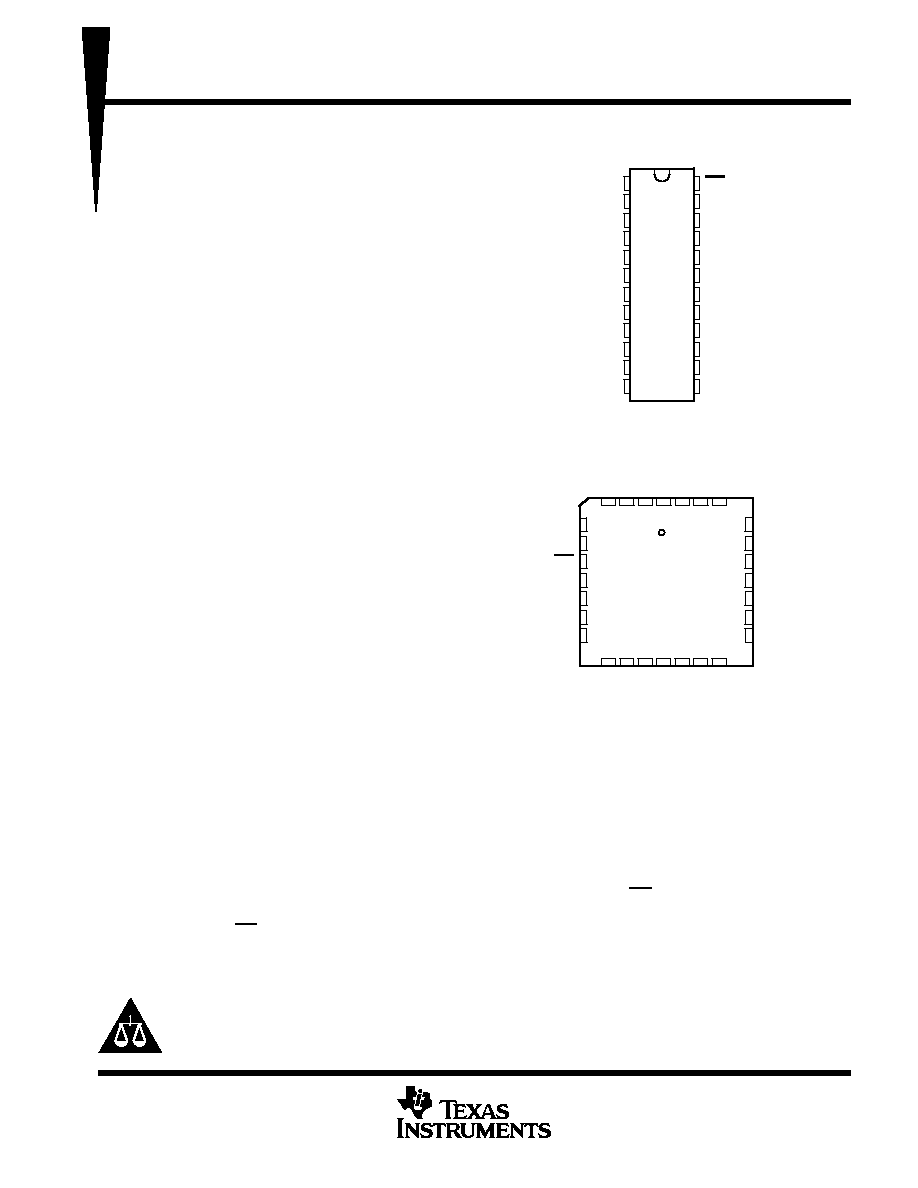
A8
TDI
TCK
NC
TMS
TDO
B8
A2
A1
OE
NC
DIR
B1
B2
4
15 16 17 18
B4
GND
NC
B5
B6
B7
A3
A4
A5
NC
28 27 26
25
24
23
22
21
20
19
12
B3
V
A6
A7
CC
SN54ABT8245 . . . JT PACKAGE
SN74ABT8245 . . . DW PACKAGE
(TOP VIEW)
SN54ABT8245 . . . FK PACKAGE
(TOP VIEW)
1
2
3
4
5
6
7
8
9
10
11
12
24
23
22
21
20
19
18
17
16
15
14
13
DIR
B1
B2
B3
B4
GND
B5
B6
B7
B8
TDO
TMS
OE
A1
A2
A3
A4
A5
V
CC
A6
A7
A8
TDI
TCK
NC No internal connection
Please be aware that an important notice concerning availability, standard warranty, and use in critical applications of
Texas Instruments semiconductor products and disclaimers thereto appears at the end of this data sheet.
On products compliant to MIL-PRF-38535, all parameters are tested
unless otherwise noted. On all other products, production
processing does not necessarily include testing of all parameters.

SN54ABT8245, SN74ABT8245
SCAN TEST DEVICES
WITH OCTAL BUS TRANSCEIVERS
SCBS124D AUGUST 1992 REVISED DECEMBER 1996
2
POST OFFICE BOX 655303
·
DALLAS, TEXAS 75265
description (continued)
In the test mode, the normal operation of the SCOPE
TM
bus transceivers is inhibited and the test circuitry is
enabled to observe and control the I/O boundary of the device. When enabled, the test circuitry can perform
boundary-scan test operations as described in IEEE Standard 1149.1-1990.
Four dedicated test pins control the operation of the test circuitry: test data input (TDI), test data output (TDO),
test mode select (TMS), and test clock (TCK). Additionally, the test circuitry performs other testing functions
such as parallel-signature analysis (PSA) on data inputs and pseudo-random pattern generation (PRPG) from
data outputs. All testing and scan operations are synchronized to the TAP interface.
The SN54ABT8245 is characterized for operation over the full military temperature range of 55
°
C to 125
°
C.
The SN74ABT8245 is characterized for operation from 40
°
C to 85
°
C.
FUNCTION TABLE
(normal mode)
INPUTS
OPERATION
OE
DIR
OPERATION
L
L
B data to A bus
L
H
A data to B bus
H
X
Isolation

SN54ABT8245, SN74ABT8245
SCAN TEST DEVICES
WITH OCTAL BUS TRANSCEIVERS
SCBS124D AUGUST 1992 REVISED DECEMBER 1996
4
POST OFFICE BOX 655303
·
DALLAS, TEXAS 75265
Terminal Functions
TERMINAL
NAME
DESCRIPTION
A1 A8
Normal-function A-bus I/O ports. See function table for normal-mode logic.
B1 B8
Normal-function B-bus I/O ports. See function table for normal-mode logic.
DIR
Normal-function direction-control input. See function table for normal-mode logic.
GND
Ground
OE
Normal-function output-enable input. See function table for normal-mode logic.
TCK
Test clock. One of four terminals required by IEEE Standard 1149.1-1990. Test operations of the device are synchronous to TCK.
Data is captured on the rising edge of TCK and outputs change on the falling edge of TCK.
TDI
Test data input. One of four terminals required by IEEE Standard 1149.1-1990. TDI is the serial input for shifting data through the
instruction register or selected data register. An internal pullup forces TDI to a high level if left unconnected.
TDO
Test data output. One of four terminals required by IEEE Standard 1149.1-1990. TDO is the serial output for shifting data through
the instruction register or selected data register.
TMS
Test mode select. One of four terminals required by IEEE Standard 1149.1-1990. TMS input directs the device through its TAP
controller states. An internal pullup forces TMS to a high level if left unconnected.
VCC
Supply voltage

SN54ABT8245, SN74ABT8245
SCAN TEST DEVICES
WITH OCTAL BUS TRANSCEIVERS
SCBS124D AUGUST 1992 REVISED DECEMBER 1996
5
POST OFFICE BOX 655303
·
DALLAS, TEXAS 75265
test architecture
Serial-test information is conveyed by means of a 4-wire test bus or TAP that conforms to IEEE Standard
1149.1-1990. Test instructions, test data, and test control signals all are passed along this serial-test bus. The
TAP controller monitors two signals from the test bus, TCK and TMS. The TAP controller extracts the
synchronization (TCK) and state control (TMS) signals from the test bus and generates the appropriate on-chip
control signals for the test structures in the device. Figure 1 shows the TAP-controller state diagram.
The TAP controller is fully synchronous to the TCK signal. Input data is captured on the rising edge of TCK and
output data changes on the falling edge of TCK. This scheme ensures data to be captured is valid for fully
one-half of the TCK cycle.
The functional block diagram shows the IEEE Standard 1149.1-1990 4-wire test bus and boundary-scan
architecture and the relationship among the test bus, the TAP controller, and the test registers. As illustrated,
the device contains an 8-bit instruction register and three test-data registers: a 36-bit boundary-scan register,
an 11-bit boundary-control register, and a 1-bit bypass register.
Test-Logic-Reset
Run-Test/Idle
Select-DR-Scan
Capture-DR
Shift-DR
Exit1-DR
Pause-DR
Update-DR
TMS = L
TMS = L
TMS = H
TMS = L
TMS = H
TMS = H
TMS = L
TMS = H
TMS = L
TMS = L
TMS = H
TMS = L
Exit2-DR
Select-IR-Scan
Capture-IR
Shift-IR
Exit1-IR
Pause-IR
Update-IR
TMS = L
TMS = L
TMS = H
TMS = L
TMS = H
TMS = H
TMS = L
TMS = H
TMS = L
Exit2-IR
TMS = L
TMS = H
TMS = H
TMS = H
TMS = L
TMS = H
TMS = L
TMS = H
TMS = H
TMS = H
TMS = L
Figure 1. TAP-Controller State Diagram
