Document Outline
- DESCRIPTION
- FEATURES
- APPLICATIONS
- PIN CONFIGURATIONS
- ORDERING INFORMATION
- PIN DESCRIPTION
- TRUTH TABLE
- VIRGIN STATE
- LOGIC FUNCTION
- FUNCTIONAL DIAGRAM
- LOGIC DIAGRAM
- DETAILS FOR REGISTERS FOR PLUS405
- COMPLEMENT ARRAY DETAIL
- ABSOLUTE MAXIMUM RATINGS
- THERMAL RATINGS
- DC ELECTRICAL CHARACTERISTICS
- AC ELECTRICAL CHARACTERISTICS
- TEST LOAD CIRCUIT
- VOLTAGE WAVEFORMS
- TIMING DIAGRAMS
- TIMING DEFINITIONS
- LOGIC PROGRAMMING
- INITIALIZATION/OE OPTION … (INIT/OE)
- INITIALIZATION OPTION … (INIT)
- ŤANDŽ ARRAY … (I), (P)
- ŤORŽ ARRAY … J-K FUNCTION … (N), (F)
- ŤCOMPLEMENTŽ ARRAY … (C)
- CLOCK OPTION … (CLK1/CLK2)
- PROGRAMMING/SOFTWARE SUPPORT
- PLUS405 PROGRAM TABLE
- SNAP RESOURCE SUMMARY DESIGNATIONS

Philips Semiconductors Programmable Logic Devices
Product specification
PLUS405-55
Programmable logic sequencer
(16
×
64
×
8)
180
October 22, 1993
8531546 11164
DESCRIPTION
The PLUS405-55 device is a bipolar,
programmable state machine of the Mealy
type. Both the AND and the OR array are
user-programmable. All 64 AND gates are
connected to the 16 external dedicated inputs
(I0 - I15) and to the feedback paths of the
8 on-chip State Registers (Q
P0
- Q
P7
). Two
complement arrays support complex
IF-THEN-ELSE state transitions with a single
product term (input variables C
0
, C
1).
All state transition terms can include True,
False and Don't Care states of the controlling
state variables. All AND gates are merged
into the programmable OR array to issue the
next-state and next-output commands to their
respective registers. Because the OR array is
programmable, any one or all of the 64
transition terms can be connected to any or
all of the State and Output Registers.
All state (Q
P0
- Q
P7
) and output (Q
F0
- Q
F7
)
registers are edge-triggered, clocked J-K
flip-flops, with Asynchronous Preset and
Reset options. The PLUS405 architecture
provides the added flexibility of the J-K toggle
function which is indeterminate on S-R
flip-flops. Each register may be individually
programmed such that a specific
Preset-Reset pattern is initialized when the
initialization pin is raised to a logic level "1".
This feature allows the state machine to be
asynchronously initialized to known internal
state and output conditions prior to
proceeding through a sequence of state
transitions. Upon power-up, all registers are
unconditionally preset to "1". If desired, the
initialization input pin (INIT) can be converted
to an Output Enable (OE) function as an
additional user-programmable feature.
Availability of two user-programmable clocks
allows the user to design two independently
clocked state machine functions consisting of
four state and four output bits each.
Order codes are listed in the Ordering
Information Table below.
FEATURES
·
66.7MHz minimum guaranteed clock rate
·
55MHz minimum guaranteed operating
frequency (1/(t
IS1
+ t
CKO1
)
·
Functional superset of PLS105/105A
·
Field-programmable (Ti-W fusible link)
·
16 input variables
·
8 output functions
·
64 transition terms
·
8-bit State Register
·
8-bit Output Register
·
2 transition Complement Arrays
·
Multiple clocks
·
Programmable Asynchronous Initialization
or Output Enable
·
Power-on preset of all registers to "1"
·
"On-chip" diagnostic test mode features for
access to state and output registers
·
950mW power dissipation (typ.)
·
TTL compatible
·
J-K or S-R flip-flop functions
·
Automatic "Hold" states
·
3-State outputs
APPLICATIONS
·
Interface protocols
·
Sequence detectors
·
Peripheral controllers
·
Timing generators
·
Sequential circuits
·
Elevator contollers
·
Security locking systems
·
Counters
·
Shift registers
PIN CONFIGURATIONS
1
2
3
4
5
6
7
8
9
10
11
12
13
14
15
16
17
18
19
20
21
22
23
24
25
26
27
28
N Package
1
2
3
4
5
6
7
8
9
10
11
12
13
14
15
16
17
18
19
20
21
22
23
24
25
26
27
28
CLK
I7
I6
I5/CLK
I4
I3
I2
I1
I0
F7
F6
F5
F4
GND
F3
F2
F1
F0
INIT/OE
I15
I14
I13
I12
I11
I10
I9
I8
VCC
CLK
I6
I7
VCC
I5/CLK
I8
I9
I4
I3
I2
I1
I0
F7
F6
F5
F4 GND F3
F2
F1 F0
INIT/OE
I15
I14
I13
I12
I11
I10
N = Plastic DIP (600mil-wide)
A = Plastic Leaded Chip Carrier
A Package
ORDERING INFORMATION
DESCRIPTION
OPERATING
FREQUENCY
ORDER CODE
DRAWING NUMBER
28-Pin Plastic Dual In-Line (600mil-wide)
55MHz (t
IS
+ t
CKO
)
PLUS40555N
0413B
28-Pin Plastic Leaded Chip Carrier
55MHz (t
IS
+ t
CKO
)
PLUS40555A
0401F

Philips Semiconductors Programmable Logic Devices
Product specification
PLUS405-55
Programmable logic sequencer
(16
×
64
×
8)
October 22, 1993
181
PIN DESCRIPTION
PIN NO.
SYMBOL
NAME AND FUNCTION
POLARITY
1
CLK1
Clock: The Clock input to the State and Output Registers. A Low-to-High transition on this
line is necessary to update the contents of both state and output registers. Pin 1 only
clocks P03 and F03 if Pin 4 is also being used as a clock.
Active-High (H)
2, 3, 59,
2627
2022
I0 I4, I7, I6
I8 I9
I13 I15
Logic Inputs: The 12 external inputs to the AND array used to program jump conditions
between machine states, as determined by a given logic sequence. True and complement
signals are generated via use of "H" and "L".
Active-High/Low
(H/L)
4
CLK2
Logic Input/Clock: A user programmable function:
·
Logic Input: A 13th external logic input to the AND array, as above.
Active-High/Low
(H/L)
·
Clock: A 2nd clock for the State Registers P47 and Output Registers F47, as above.
Note that input buffer I5 must be deleted from the AND array (i.e., all fuse locations "Don't
Care") when using Pin 4 as a Clock.
Active-High (H)
23
I12
Logic/Diagnostic Input: A 14th external logic input to the AND array, as above, when
exercising standard TTL or CMOS levels. When I12 is held at +10V, device outputs F0F7
reflect the contents of State Register bits P0P7. The contents of each Output Register
remains unaltered.
Active-High/Low
(H/L)
24
I11
Logic/Diagnostic Input: A 15th external logic input to the AND array, as above, when
exercising standard TTL levels. When I11 is held at +10V, device outputs F0F7 become
direct inputs for State Register bits P0P7; a Low-to-High transition on the appropriate
clock line loads the values on pins F0F7 into the State Register bits P0P7. The contents
of each Output Register remains unaltered.
Active-High/Low
(H/L)
25
I10
Logic/Diagnostic Input: A 16th external logic input to the AND array, as above, when
exercising standard TTL levels. When I10 is held at +10V, device outputs F0F7 become
direct inputs for Output Register bits Q0Q7; a Low-to-High transition on the appropriate
clock line loads the values on pins F0F7 into the Output Register bits Q0Q7. The
contents of each State Register remains unaltered.
Active-High/Low
(H/L)
1013
1518
F0 F7
Logic Outputs/Diagnostic Outputs/Diagnostic Inputs: Eight device outputs which
normally reflect the contents of Output Register Bits Q0Q7, when enabled. When I12 is
held at +10V, F0F7 = (P0P7). When I11 is held at +10V, F0F7 become inputs to State
Register bits P0P7. When I10 is held at +10V, F0F7 become inputs to Output Register
bits Q0Q7.
Active-High (H)
19
INIT/OE
Initialization or Output Enable Input: A user programmable function:
·
Initialization: Provides an asynchronous preset to logic "1" or reset to logic "0" of all
State and Output Register bits, determined individually for each register bit through user
programming. INIT overrides Clock, and when held High, clocking is inhibited and F0F7
and P0P7 are in their initialization state. Normal clocking resumes with the first full clock
pulse following a High-to-Low clock transition, after INIT goes Low. See timing definition for
t
NVCK
and t
VCK
.
Active-High (H)
·
Output Enable: Provides an output enable function to buffers F0F7 from the Output
Registers.
Active-Low (L)

Philips Semiconductors Programmable Logic Devices
Product specification
PLUS405-55
Programmable logic sequencer
(16
×
64
×
8)
October 22, 1993
182
TRUTH TABLE
1, 2, 3, 4, 5, 6, 7
OPTION
V
CC
INIT
OE
I10
I11
I12
CK
J
K
Q
P
Q
F
F
H
*
*
*
X
X
X
H/L
H/L
Q
F
L
+10V
X
X
X
X
Q
P
L
L
L
+10V
X
X
X
X
Q
P
H
H
L
X
+10V
X
X
X
L
Q
F
L
L
X
+10V
X
X
X
H
Q
F
H
L
X
X
+10V
X
X
X
Q
P
Q
F
Q
P
L
X
X
X
X
X
X
Q
P
Q
F
Q
F
H
X
X
*
X
X
X
Q
P
Q
F
Hi-Z
+5V
X
+10V
X
X
X
X
Q
P
L
L
X
+10V
X
X
X
X
Q
P
H
H
X
X
+10V
X
X
X
L
Q
F
L
X
X
+10V
X
X
X
H
Q
F
H
L
X
X
+10V
X
X
X
Q
P
Q
F
Q
P
L
X
X
X
X
X
X
Q
P
Q
F
Q
F
L
X
X
X
L
L
Q
P
Q
F
Q
F
L
X
X
X
L
H
L
L
L
L
X
X
X
H
L
H
H
H
L
X
X
X
H
H
Q
P
Q
F
Q
F
X
X
X
X
X
X
X
X
H
H
NOTES:
1. Positive Logic:
S/R (or J/K) = T
0
+ T
1
+ T
2
+ . . . T
63
T
n
= (C0, C1) (I0, I1, I2, . . .) (P0, P1, . . . P7)
2. Either Initialization (Active-High) or Output Enable (Active-Low) are available, but not both. The desired function is a user-programmable
option.
3.
denotes transition from Low-to-High level.
4. * = H or L or +10V
5. X = Don't Care (<5.5V)
6. H/L implies that either a High or a Low can occur, depending upon user-programmed selection (each State and Output Register individually
programmable).
7. When using the F
n
pins as inputs to the State and Output Registers in diagnostic mode, the F buffers are 3-Stated and the indicated levels
on the output pins are forced by the user.
VIRGIN STATE
A factory-shipped virgin device contains all
fusible links intact, such that:
1. INIT/OE is set to INIT. In order to use the
INIT function, the user must select either
the PRESET or the RESET option for
each flip-flop. Note that regardless of the
user-programmed initialization, or even if
the INIT function is not used, all registers
are preset to "1" by the power-up
procedure.
2. All transition terms are inactive (0).
3. All S/R (or J/K) flip-flop inputs are
disabled (0).
4. The device can be clocked via a Test
Array preprogrammed with a standard
test pattern.
5. Clock 2 is inactive.
LOGIC FUNCTION
0
1
0
0
0
1
STATE REGISTER
SR
Sn + 1
PRESENT STATE
A
B
C
. . .
NEXT STATE
Q2
Q1
Q0
SET Q0: J0 = (Q2
Q1
Q0)
A
B
C . . .
K0 = 0
RESET Q1: J1 = 0
K1 = (Q3
Q2
Q1
Q0)
A
B
C . . .
HOLD Q2: J2 = 0
K2 = 0
1
0
Q3
RESET Q3: J3 = (Q3
Q2
Q1
Q0)
A
B
C . . .
K3 = (Q3
Q2
Q1
Q0)
A
B
C . . .
Philips Semiconductors Programmable Logic Devices
Product specification
PLUS405-55
Programmable logic sequencer
(16
×
64
×
8)
October 22, 1993
183
FUNCTIONAL DIAGRAM
P63
P0
15
I
X2
I/CLK
J
K
P
R
Q
(4)
J
K
P
R
Q
(4)
J
K
P
R
Q
(4)
J
K
P
R
Q
(4)
4
F
CK
F
4
4
INIT/OE
4
4
4
4
4
4
4

Philips Semiconductors Programmable Logic Devices
Product specification
PLUS405-55
Programmable logic sequencer
(16
×
64
×
8)
October 22, 1993
184
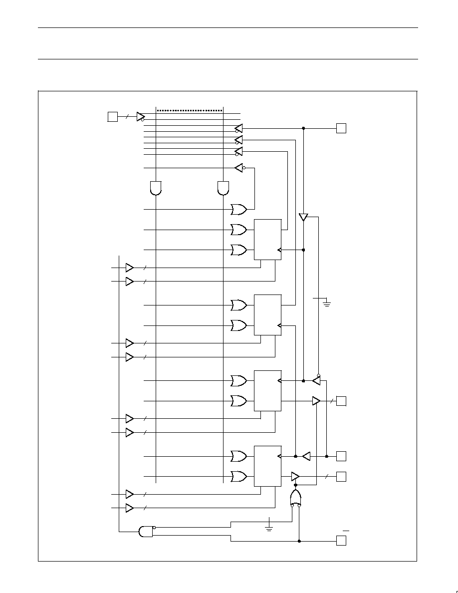
LOGIC DIAGRAM
DETAIL A
DETAIL B
DETAIL C
DETAIL D
9
8
7
6
5
4
3
2
1
27
26
25
24
23
22
21
20
19
18
17
16
15
13
12
11
10
I0
I1
I2
I3
I4
I6
I7
I8
I9
I10
I11
I12
I13
I14
I15
I5/CLK
INIT/OE
F0
F1
F2
F3
F4
F5
F6
F7
CLK
NOTE:
Denotes a programmable fuse location.

Philips Semiconductors Programmable Logic Devices
Product specification
PLUS405-55
Programmable logic sequencer
(16
×
64
×
8)
October 22, 1993
185
DETAILS FOR REGISTERS FOR PLUS405
STATE REGISTERS
J
K
Q
P
R
CLK
TO INIT LINE
TO AND
ARRAY
Detail B
19
INIT/OE
Detail A
Ps
OUTPUT REGISTERS
J
K
Q
P
R
CLK
TO INIT LINE
Detail C
Fn
FROM
PIN 1 CLK
FROM PIN 4
(I5/CLK)
Detail D
COMPLEMENT ARRAY DETAIL
P63
P62
P2
P1
P0
A
B
C0
D
E
C1
C1
C0
TO OR ARRAY
The Complement Array is a special
sequencer feature that is often used for
detecting illegal states. It is also ideal for
generating IF-THEN-ELSE logic statements
with a minimum number of product terms.
The concept is deceptively simple. If you
subscribe to the theory that the expressions
(/A
* /B
* /C) and (A + B + C) are equivalent,
you will begin to see the value of this single
term NOR array.
The Complement Array is a single OR gate
with inputs from the AND array. The output of
the Complement Array is inverted and fed
back to the AND array (NOR). The output of
the array will be Low if any one or more of the
AND terms connected to it are active (High).
If, however, all the connected terms are
inactive (Low), which is a classic unknown
state, the output of the Complement Array will
be High.
Consider the Product Terms A, B and D that
represent defined states. They are also
connected to the input of the Complement
Array. When the condition (not A and not B
and not D) exists, the Complement Array will
detect this and propagate an Active-High
signal to the AND array. This signal can be
connected to Product Term E, which could be
used in turn to reset the state machine to a
known state. Without the Complement Array,
one would have to generate product terms for
all unknown or illegal states. With very
complex state machines, this approach can
be prohibitive, both in terms of time and
wasted resources.
Note that the PLUS405 sequencers have 2
Complement Arrays which allow the user to
design 2 independent Complement functions.
This is particularly useful if 2 independent
state machines have been implemented on
one device.
Note that use of the Complement Array adds
an additional delay path through the device.
Please refer to the AC Electrical
Characteristics for details.

TEMPERATURE
Maximum junction
150
°
C
Maximum ambient
75
°
C
Allowable thermal rise
75
°
C
ambient to junction
Philips Semiconductors Programmable Logic Devices
Product specification
PLUS405-55
Programmable logic sequencer
(16
×
64
×
8)
October 22, 1993
186
ABSOLUTE MAXIMUM RATINGS
1
THERMAL RATINGS
SYMBOL
PARAMETER
RATINGS
UNIT
V
CC
Supply voltage
+7
V
DC
V
IN
Input voltage
+5.5
V
DC
V
OUT
Output voltage
+5.5
V
DC
I
IN
Input currents
30 to +30
mA
I
OUT
Output currents
+100
mA
T
amb
Operating temperature range
0 to +75
°
C
T
stg
Storage temperature range
65 to +150
°
C
NOTES:
1. Stresses above those listed may cause malfunction or permanent damage to the device. This
is a stress rating only. Functional operation at these or any other condition above those
indicated in the operational and programming specification of the device is not implied.
DC ELECTRICAL CHARACTERISTICS
0
°
C
T
amb
+75
°
C, 4.75V
V
CC
5.25V
LIMITS
SYMBOL
PARAMETER
TEST CONDITIONS
MIN
TYP
1
MAX
UNIT
Input voltage
2
V
IH
High
V
CC
= MAX
2.0
V
V
IL
Low
V
CC
= MIN
0.8
V
V
IC
Clamp
3
V
CC
= MIN, I
IN
= 12mA
0.8
1.2
V
Output voltage
2
V
OH
High
V
CC
= MIN, I
OH
= 2mA
2.4
V
V
OL
Low
V
CC
= MIN, I
OL
= 9.6mA
0.35
0.45
V
Input current
I
IH
High
V
CC
= MAX, V
IN
= V
CC
<1
30
µ
A
I
IL
Low
V
CC
= MAX, V
IN
= 0.45V
20
250
µ
A
Output current
I
O(OFF)
Hi-Z state
V
CC
= MAX, V
OUT
= 2.7V
1
40
µ
A
V
CC
= MAX, V
OUT
= 0.45V
1
40
µ
A
I
OS
Short circuit
3, 4
V
OUT
= 0V
15
70
mA
I
CC
V
CC
supply current
5
V
CC
= MAX
190
225
mA
Capacitance
C
IN
Input
V
CC
= 5.0V, V
IN
= 2.0V
8
pF
C
OUT
Output
V
CC
= 5.0V, V
OUT
= 2.0V
10
pF
NOTES:
1. All typical values are at V
CC
= 5V. T
amb
= +25
°
C.
2. All voltage values are with respect to network ground terminal.
3. Test one at a time.
4. Duration of short-circuit should not exceed one second.
5. I
CC
is measured with the INIT/OE input grounded, all other inputs at 4.5V and the outputs open.

Philips Semiconductors Programmable Logic Devices
Product specification
PLUS405-55
Programmable logic sequencer
(16
×
64
×
8)
October 22, 1993
187
AC ELECTRICAL CHARACTERISTICS
R
1
= 470
, R
2
= 1k
, C
L
= 30pF, 0
°
C
T
amb
+75
°
C, 4.75V
V
CC
5.25V
LIMITS
SYMBOL
PARAMETER
FROM
TO
MIN
TYP
1
MAX
UNIT
Pulse width
t
CKH1
Clock High; CLK1 (Pin 1)
CK+
CK
7.5
6
ns
t
CKL1
Clock Low; CLK1 (Pin 1)
CK
CK+
7.5
6
ns
t
CKP1
CLK1 Period
CK+
CK+
15
12
ns
t
CKH2
Clock High; CLK2 (Pin 4)
CK+
CK
7.5
6
ns
t
CKL2
Clock Low; CLK2 (Pin 4)
CK
CK+
7.5
6
ns
t
CKP2
CLK2 Period
CK +
CK +
15
12
ns
t
INITH
Initialization pulse
INIT
INIT+
14
12
ns
Setup time
t
IS1
Input
Input
±
CK+
10
9
ns
t
IS2
Input
(through Complement Array)
Input
±
CK+
18
15
ns
t
VS
Power-on preset
V
CC
+
CK
0
10
ns
t
VCK
Clock resume
(after Initialization)
INIT
CK
0
5
ns
t
NVCK
Clock lockout
(before Initialization)
CK
INIT
12
5
ns
Hold time
t
IH
Input
CK+
Input
±
0
5
ns
Propagation delay
t
CKO1
Clock1 (Pin 1)
CK1+
Output
±
6.5
8
ns
t
CKO2
Clock2 (Pin 4)
CK2+
Output
±
7.0
8
ns
t
OE
2
Output Enable
OE
Output
6.5
8
ns
t
OD
2
Output Disable
OE+
Output +
6.5
8
ns
t
INIT
Initialization
INIT+
Output +
12
18
ns
t
PPR
Power-on Preset
V
CC
+
Output +
0
10
ns
Notes on following page

Philips Semiconductors Programmable Logic Devices
Product specification
PLUS405-55
Programmable logic sequencer
(16
×
64
×
8)
October 22, 1993
188
AC ELECTRICAL CHARACTERISTICS (Continued)
R
1
= 470
, R
2
= 1k
, C
L
= 30pF, 0
°
C
T
amb
+75
°
C, 4.75V
V
CC
5.25V
LIMITS
SYMBOL
PARAMETER
FROM
TO
MIN
TYP
1
MAX
UNIT
Frequency of operation
f
MAX1
CLK1; (without Complement Array)
1
t
IS1
)
t
CKO1
Input
±
Output
±
55.6
64.5
MHz
f
MAX2
CLK2; (without Complement Array)
1
t
IS1
)
t
CKO2
Input
±
Output
±
55.6
62.5
MHz
f
MAX3
CLK1; (with Complement Array)
1
t
IS2
)
t
CKO1
Input through
Complement
Array
±
Output
±
38.5
46.5
MHz
f
MAX4
CLK2; (with Complement Array)
1
t
IS2
)
t
CKO2
Input through
Complement
Array
±
Output
±
38.5
45.5
MHz
f
MAX5
1
t
CKL
)
t
CKH
Internal feedback without Complement
Array (CLK1 or CLK2)
Register
Output
±
Register
Input
±
66.7
83.3
MHz
f
MAX6
1
t
IS2
Internal feedback with
Complement Array (CLK1 or CLK2)
Register
Output
through
Complement
Array
±
Register
Input
±
55.6
66.7
MHz
f
CLK
Minimum guaranteed Clock frequency
CK +
CK +
66.7
83.3
MHz
NOTES:
1. All typical values are at V
CC
= 5V, T
amb
= +25
°
C.
2. For 3-State output; output enable times are tested with C
L
= 30pF to the 1.5V level, and S
1
is open for high-impedance to High tests and
closed for high-impedance to Low tests. Output disable times are tested with C
L
= 5pF. High-to-High impedance tests are made to an output
voltage of V
T
= (V
OH
0.5V) with S
1
open, and Low-to-High impedance tests are made to the V
T
= (V
OL
+ 0.5V) level with S
1
closed.
3. All propagation delays and setup times are measured and specified under worst case conditions.
TEST LOAD CIRCUIT
VOLTAGE WAVEFORMS
MEASUREMENTS:
All circuit delays are measured at the +1.5V level of
inputs and outputs, unless otherwise specified.
Input Pulses
90%
10%
2.5ns
90%
10%
+3.0V
+3.0V
0V
0V
tR
tF
2.5ns
2.5ns
2.5ns
+5V
CL
R1
R2
S1
GND
F7
F0
INPUTS
I0
I15
CK
OUTPUTS
C2
C1
DUT
NOTE:
C1 and C2 are to bypass VCC to GND.
VCC
INIT/OE
Philips Semiconductors Programmable Logic Devices
Product specification
PLUS405-55
Programmable logic sequencer
(16
×
64
×
8)
October 22, 1993
189
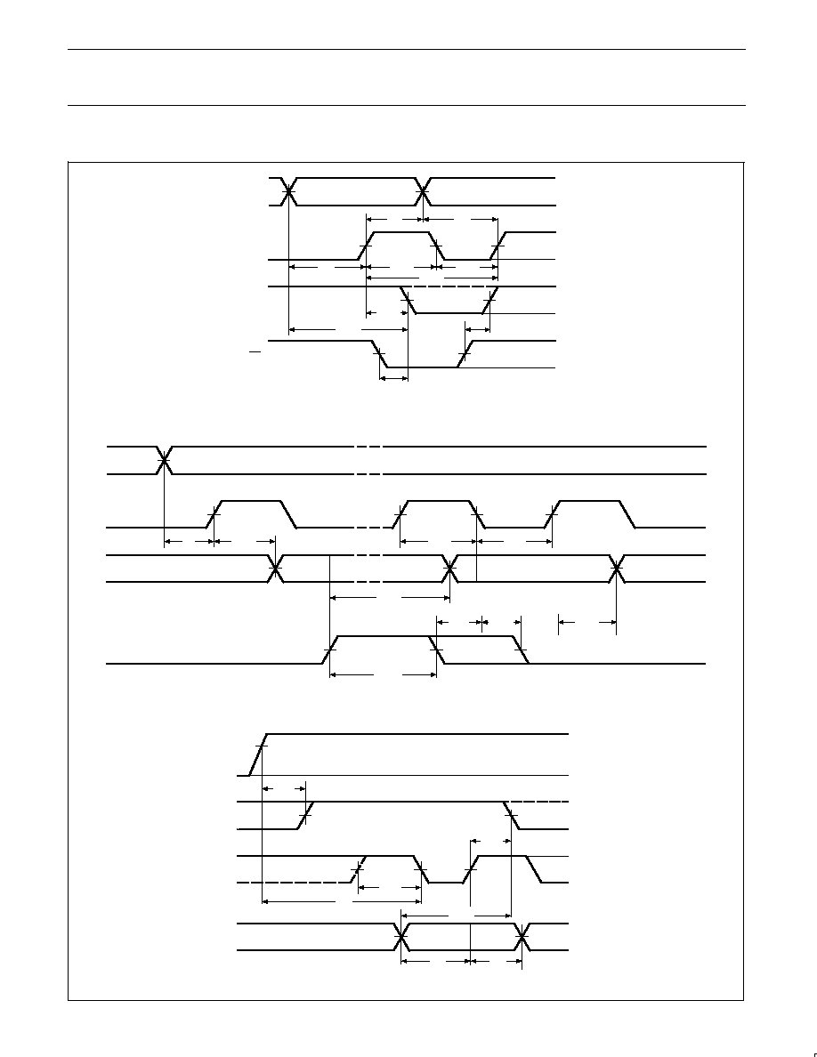
TIMING DIAGRAMS
fMAX
tCKO
tIH
ÇÇÇÇÇ
ÇÇÇÇÇ
ÇÇÇÇÇ
ÇÇÇÇÇ
tNVCK
tVCK
tCKO
Sequential Mode
Asynchronous Initialization
Power-On Preset
I0 I15
F0 F7
CLK
OE
ÇÇÇÇÇÇ
ÇÇÇÇÇÇ
ÇÇÇÇÇÇ
ÇÇÇÇÇÇ
I0 I15
F0 F7
CLK
INIT
1.5V
1.5V
1.5V
1.5V
1.5V
1.5V
1.5V
1.5V
1.5V
1.5V
+3V
+3V
+3V
0V
0V
0V
VOH
VOL
tCKH
tCKL
tIS
tINIT
tINITH
tCKO
4.5V
1.5V
tPPR
VCC
F0 F7
CLK
I0 I15
+5V
0V
VOH
VOL
+3V
0V
+3V
0V
1.5V
1.5V
1.5V
1.5V
1.5V
1.5V
tIS
tCKH
tVS
[Fn] = 1
[Fn] + 1
tCKO
1.5V
1.5V
1.5V
1.5V
1.5V
1.5V
1.5V
1.5V
1.5V
+3V
+3V
+3V
0V
0V
0V
VOH
VOL
tIH
tIS
tCKL
tCKH
tIS
fMAX
tOD
tOE
tCKP

Philips Semiconductors Programmable Logic Devices
Product specification
PLUS405-55
Programmable logic sequencer
(16
×
64
×
8)
October 22, 1993
190
TIMING DIAGRAMS (Continued)
( )
tCKO
tRH
tRJS
ÉÉÉÉÉ
ÉÉÉÉÉ
ÉÉÉÉÉ
ÉÉÉÉÉ
tCKO
tIH
ÉÉÉ
ÉÉÉ
ÉÉÉ
ÉÉÉ
ÉÉÉÉ
ÉÉÉÉ
ÉÉÉÉ
ÉÉÉÉ
Diagnostic Mode State Register Outputs
Diagnostic Mode State Register Input Jam
Diagnostic Mode Output Register Input Jam
ÉÉÉÉÉÉÉÉÉ
ÉÉÉÉÉÉÉÉÉ
ÉÉÉÉÉÉÉÉÉ
ÉÉÉÉÉÉÉÉÉ
F0 F7
1.5V
tIS
VOH
VOL
+3V
0V
1.5V
1.5V
1.5V
8.0V
8.0V
1.5V
1.5V
1.5V
1.5V
0V
+10V
+3V
0V
+3V
0V
VOH
VOL
I12
I0 I11,
I13 I15
CLK
Q0 Q7
OE
tCKH
INTERNAL
STATE REG.
(PS)
tSRE
tSRD
(Fn)
(Fn+1)
(Fn+1)
(NS)
(NS)
8.0V
8.0V
I11
F0 F7
(INPUTS)
+10V
+3V
0V
+3V
0V
+3V
0V
VOH
VOL
ÉÉÉÉÉÉÉÉÉÉÉÉÉÉÉÉ
ÉÉÉÉÉÉÉÉÉÉÉÉÉÉÉÉ
ÉÉÉÉÉÉÉÉÉÉÉÉÉÉÉÉ
ÉÉÉÉÉÉÉÉÉÉÉÉÉÉÉÉ
tRJH
1.5V
1.5V
1.5V
1.5V
tIS
tCKH
(FORCED DIN)
(DIN)
CLK
QP
STATE
REG.
( )
ÉÉÉÉÉ
ÉÉÉÉÉ
ÉÉÉÉÉ
ÉÉÉÉÉ
ÉÉÉÉÉÉÉÉÉ
ÉÉÉÉÉÉÉÉÉ
ÉÉÉÉÉÉÉÉÉ
ÉÉÉÉÉÉÉÉÉ
ÉÉÉÉÉÉÉÉÉÉÉÉÉÉÉÉ
ÉÉÉÉÉÉÉÉÉÉÉÉÉÉÉÉ
ÉÉÉÉÉÉÉÉÉÉÉÉÉÉÉÉ
ÉÉÉÉÉÉÉÉÉÉÉÉÉÉÉÉ
tCKO
tRH
tRJS
8.0V
8.0V
I10
F0 F7
(INPUTS)
+10V
+3V
0V
+3V
0V
+3V
0V
VOH
VOL
tRJH
1.5V
1.5V
1.5V
1.5V
tIS
tCKH
(FORCED DIN)
(DIN)
CLK
QF
STATE
REG.

Philips Semiconductors Programmable Logic Devices
Product specification
PLUS405-55
Programmable logic sequencer
(16
×
64
×
8)
October 22, 1993
191
TIMING DEFINITIONS
SYMBOL
PARAMETER
t
CKH1, 2
Width of input clock pulse.
t
CKP1, 2
Minimum guaranteed clock
period.
t
IS1
Required delay between
beginning of valid input and
positive transition of Clock.
t
CKO1, 2
Delay between positive
transition of Clock and when
Outputs become valid (with
INIT/OE Low).
t
PPR
Delay between V
CC
(after
power-on) and when Outputs
become preset at "1".
t
IS2
Required delay between
beginning of valid Input and
positive transition of Clock,
when using optional
Complement Array (two
passes necessary through
the AND Array).
t
RJH
Required delay between
positive transition of clock,
and return of input I10, I11 or
I12 from Diagnostic Mode
(10V).
f
MAX1, 2
Minimum guaranteed
operating frequency; input to
output (CLK1 and CLK2).
f
MAX3, 4
Minimum guaranteed
operating frequency; input
through Complement Array,
to output (CLK1 and CLK2).
f
MAX5
Minimum guaranteed internal
operating frequency; with
internal feedback from state
register to state register.
SYMBOL
PARAMETER
f
MAX6
Minimum guaranteed internal
operating frequency with
Complement Array, with
internal feedback from state
register through Complement
Array, to state register.
f
CLK
Minimum guaranteed clock
frequency (register toggle
frequency).
t
CKL1, 2
Interval between clock
pulses.
t
IH
Required delay between
positive transition of Clock
and end of valid Input data.
t
OE
Delay between beginning of
Output Enable Low and when
Outputs become valid.
t
SRE
Delay between input I12
transition to Diagnostic Mode
and when the Outputs reflect
the contents of the State
Register.
t
RJS
Required delay between
inputs I11, I10 or I12
transition to Diagnostic Mode
(10V), and when the output
pins become available as
inputs.
t
NVCK
Required delay between the
negative transition of the
clock and the negative
transition of the
Asynchronous Initialization to
guarantee that the clock edge
is not detected as a valid
negative transition.
SYMBOL
PARAMETER
t
INITH
Width of initialization input
pulse.
t
VS
Required delay between V
CC
(after power-on) and negative
transition of Clock preceding
first reliable clock pulse.
t
OD
Delay between beginning of
Output Enable High and
when Outputs are in the
OFF-state.
t
INIT
Delay between positive
transition of Initialization and
when Outputs become valid.
t
SRD
Delay between input I12
transition to Logic mode and
when the Outputs reflect the
contents of the Output
Register.
t
RH
Required delay between
positive transition of Clock
and end of valid Input data
when jamming data into State
or Output Registers in
diagnostic mode.
t
VCK
Required delay between
negative transition of
Asynchronous Initialization
and negative transition of
Clock preceding first reliable
clock pulse.

PROGRAMMING THE PLUS405:
The PLUS405 has a power-up preset feature. This feature insures that the device will power-up
in a known state with all register elements (State and Output Register) at logic High (H). When
programming the device it is important to realize this is the initial state of the device. You
must
provide a next state jump if you do not wish to use all Highs (H) as the present state.
OPTION
CODE
L
OE
OPTION
CODE
H
INITIALIZATION1
INIT
(ALWAYS
ENABLED)
E = 1
INIT/OE
INIT = 0
E
INIT/OE
(INITIALIZATION
DISABLED)
Philips Semiconductors Programmable Logic Devices
Product specification
PLUS405-55
Programmable logic sequencer
(16
×
64
×
8)
October 22, 1993
192
LOGIC PROGRAMMING
INITIALIZATION/OE OPTION (INIT/OE)
The PLUS405-55 is fully supported by
industry standard (JEDEC compatible) PLD
CAD tools, including Philips Semiconductors
SNAP design software package. ABEL
TM
and
CUPL
TM
design software packages also
support the PLUS405-55 architecture.
All packages allow Boolean and state
equation entry formats. SNAP, ABEL and
CUPL also accept, as input, schematic
capture format.
PLUS405-55 logic designs can also be
generated using the program table entry
format, which is detailed on the following
pages. This program table entry format is
supported by SNAP only.
To implement the desired logic functions,
each logic variable (I, B, P, S, T, etc.) from the
logic equations is assigned a symbol. TRUE,
COMPLEMENT, PRESET, RESET, OUTPUT
ENABLE, INACTIVE, etc., symbols are
defined below.
INITIALIZATION OPTION (INIT)
CODE
O
ACTION
INDETERMINATE4
CODE
ACTION
CODE
ACTION
PRESET
H
RESET
L
CODE
ACTION
INDETERMINATE4
INIT
P
R
INIT
P
R
INIT
P
R
INIT
P
R
INIT
P
R
"AND" ARRAY (I), (P)
CODE
O
STATE
INACTIVE1,
2
CODE
STATE
CODE
STATE
CODE
STATE
I, P
H
I, P
L
DON'T CARE
Tn
i, p
I, P
Tn
I, P
Tn
I, P
Tn
I, P
Tn
I, P
i, p
i, p
i, p
i, p
i, p
i, p
i, p
Notes are on next page.
ABEL is a trademark of Data I/O Corp.
CUPL is a trademark of Logical Devices, Inc.

Philips Semiconductors Programmable Logic Devices
Product specification
PLUS405-55
Programmable logic sequencer
(16
×
64
×
8)
October 22, 1993
193
"OR" ARRAY J-K FUNCTION (N), (F)
CODE
ACTION
CODE
ACTION
SET
H
RESET
L
N, F
N, F
Tn
J
Q
K
CODE
ACTION
TOGGLE1
,
6
O
N, F
N, F
Tn
J
Q
K
N, F
N, F
Tn
J
Q
K
N, F
N, F
Tn
J
Q
K
CODE
ACTION
NO CHANGE
"COMPLEMENT" ARRAY (C)
CODE
O
ACTION
INACTIVE1,
3
CODE
ACTION
CODE
ACTION
CODE
ACTION
GENERATE
A
PROPAGATE
·
TRANSPARENT
Tn
c
c
Tn
c
Tn
c
Tn
c
c
c
c
CLOCK OPTION (CLK1/CLK2) PROGRAMMING/SOFTWARE SUPPORT
OPTION
CODE
L
CLK1 ONLY1
CLK2
CLK1
OPTION
CODE
H
CLK1 and CLK25
CLK2
CLK1
Refer to Section 9
(Development Software)
and Section 10
(Third-party Programmer/
Software Support) of this data handbook for additional
information.
NOTES:
1. This is the initial unprogrammed state of all links.
2. Any gate T
n
will be unconditionally inhibited if any one of its I or P link pairs is left intact.
3. To prevent oscillations, this state is not allowed for C link pairs coupled to active gates T
n
.
4. These states are not allowed when using INITIALIZATION option.
5. Input buffer I5 must be deleted from the AND array (i.e., all fuse locations "Don't Care") when using second clock option.
6. A single product term cannot drive more than 8 registers by itself when used in TOGGLE mode.

Philips Semiconductors Programmable Logic Devices
Product specification
PLUS405-55
Programmable logic sequencer
(16
×
64
×
8)
October 22, 1993
194
PLUS405 PROGRAM TABLE
NOTES:
1.
The device is shipped with all links initially intact. Thus, a background of "0" for all Terms, and an "H" for the IN/E and H for the clock option, exists in the table, shown BLANK instead
for clarity.
2.
Unused Cn Im, and Ps bits are normally programmed Don't Care (--).
3.
Unused Transition Terms can be left blank for future code modification, or programmed as (--) for maximum speed.
INACTIVE OR
TOGGLE
N7
0
1
2
3
4
5
6
7
8
9
10
11
12
13
14
15
16
17
18
19
20
21
22
23
24
25
26
27
28
29
30
31
32
33
34
35
36
37
38
39
40
41
42
43
44
45
46
47
48
49
50
51
52
53
54
55
56
57
58
59
60
61
62
63
PIN NO.
PIN
LABELS
2
0
2
1
2
2
2
3
2
4
2
5
2
6
2
7
2
3
4
5
6
7
8
9
1
0
1
1
1
2
1
3
1
5
1
6
1
7
1
8
C1 C0
COMP.
ARRAY
INPUT (Im)
AND
PRESENT STATE (Ps)
NEXT STATE (Ns)
OR
OUTPUT (Fr)
CLOCK 1/2
INITIALIZATION/OUTPUT ENABLE
CUST
OMER NAME
PHILIPS DEVICE #
CUST
OMER SYMBOLIZED P
AR
T
#
CF (XXXX)
REV
DA
TE
PROGRAM
T
ABLE
I15 I14 I13 I12 I11 I10 I9
I8
I7 I6
I5
I4
I3
I2 I1
I0 P7 P6 P5 P4 P3 P2 P1 P0
N6 N5 N4 N3 N2 N1 N0 F7 F6 F5 F4 F3 F2 F1 F0
OPTIONS
OR
AND
INIT
OE
CLK1 ONLY
CLK1 AND 2
H
L
L
H
INIT/OE
CLK1/
CLK2
Ns, Fr
SET
RESET
NO CHANGE
L
H
0
INACTIVE
GENERATE
PROPAGATE
TRANSPARENT
0
A
·
Cn
INACTIVE
I, P
I, P
DON'T CARE
0
H
Im, Ps
L

Philips Semiconductors Programmable Logic Devices
Product specification
PLUS405-55
Programmable logic sequencer
(16
×
64
×
8)
October 22, 1993
195
SNAP RESOURCE SUMMARY DESIGNATIONS
AND
P63
P0
15
I
X2
I/CLK
J
K
P
R
Q
(4)
J
K
P
R
Q
(4)
J
K
P
R
Q
(4)
J
K
P
R
Q
(4)
4
F
CK
F
4
4
INIT/OE
4
4
4
4
4
4
4
DIN405
NIN405
JKFF405
CK405
CK405
OUT405
OUT405
NOR
DIN405
NIN405