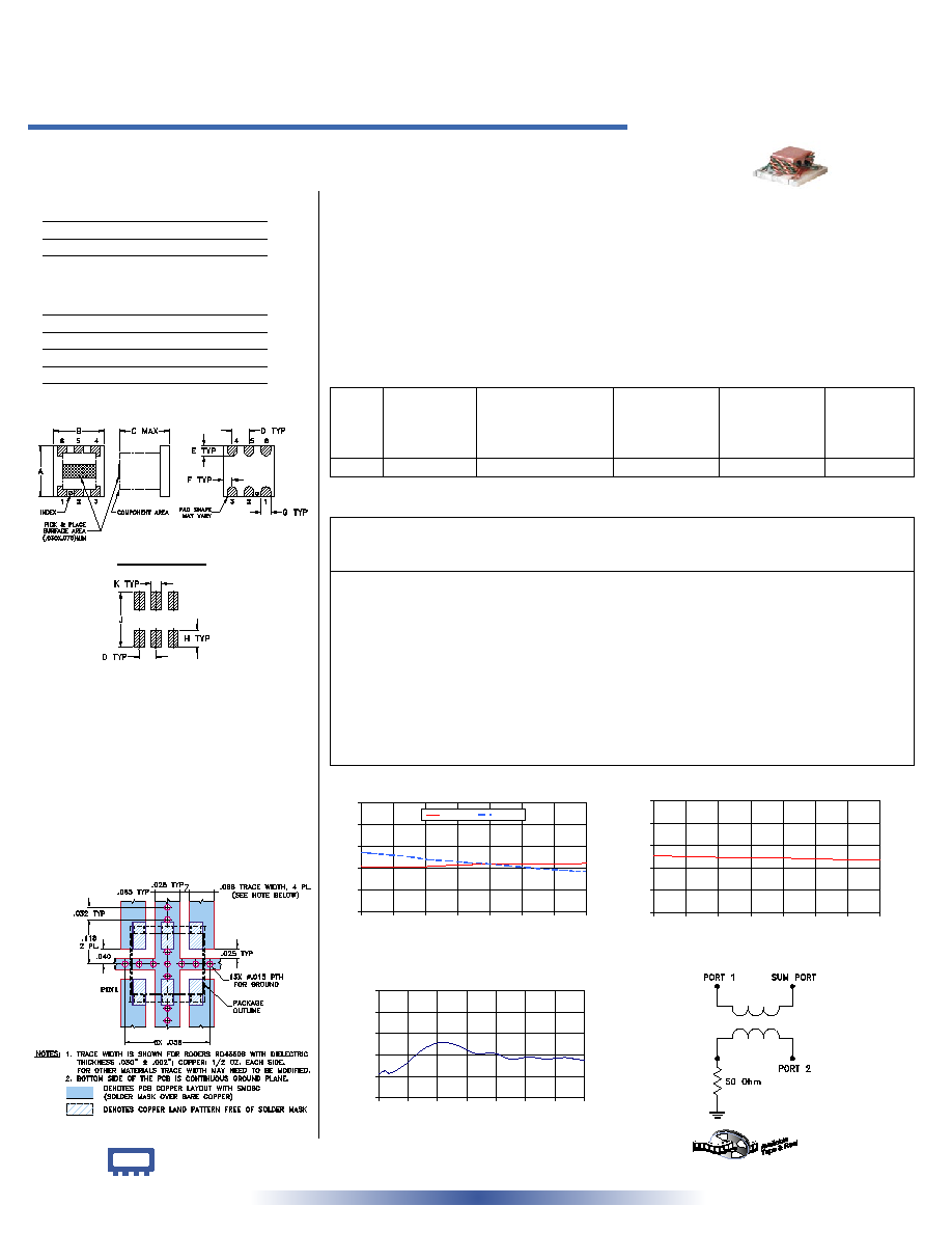
A
B
C
D
E
F
.200
.200
.200
.075
.050
.025
5.08
5.08
5.08
1.91
1.27
0.64
G
H
J
K
wt
.026
.070
.220
.035
grams
0.66
1.78
5.59
0.89
0.15
Frequency
(MHz)
Insertion Loss
(dB)
Amplitude
Unbalance
(dB)
Isolation
(dB)
Phase
Unbalance
(deg.)
VSWR
S
VSWR
1
VSWR
2
S-1
S-2
HPQ-10
INSERTION LOSS
2.0
2.6
3.2
3.8
4.4
5.0
900
910
920
930
940
950
960
970
FREQUENCY (MHz)
INSERTION
LOSS
(dB)
S-1(dB)
S-2(dB)
INTERNET
http://www.minicircuits.com
P.O. Box 350166, Brooklyn, New York 11235-0003 (718) 934-4500 Fax (718) 332-4661
Distribution Centers NORTH AMERICA 800-654-7949 � 417-335-5935 � Fax 417-335-5945 � EUROPE 44-1252-832600 � Fax 44-1252-837010
Mini-Circuits
�
Mini-Circuits ISO 9001 & ISO 14001 Certified
Typical Performance Data
Splitter Electrical Specifications
Maximum Ratings
Pin Connections
SUMPORT
3
PORT 1 (0�)
6
PORT 2 (+90�)
4
GROUND
2,5
50 OHM TERM EXTERNAL
1
Operating Temperature
-40�C to 85�C
Storage Temperature
-55�C to 100�C
Power Input (as a splitter)
1W max.
HPQ-10
2 Way-90� 50 900 to 970 MHz
Power Splitter/Combiner
REV. A
M102713
HPQ-10
ED-7075
RVN/TD/CP
060817
Surface Mount
Features
� low insertion loss, 0.25 dB typ.
� good isolation, 20 dB typ.
� excellent input VSWR, 1.17:1 typ.;
output VSWR, 1.25:1 typ.
� aqueous washable
Applications
� cellular
� GSM
� modulators
� matching amplifiers
CASE STYLE: AT577
PRICE: $6.95 ea. QTY (10-49)
HPQ-10
ISOLATION
15
17
19
21
23
25
900
910
920
930
940
950
960
970
FREQUENCY (MHz)
ISOLATION (dB)
HPQ-10
PHASE UNBALANCE
89.0
89.4
89.8
90.2
90.6
91.0
900
910
920
930
940
950
960
970
FREQUENCY (MHz)
P
H
A
S
E
U
N
B
A
L
A
N
C
E
(
D
e
g
.
)
electrical schematic
Outline Drawing
Outline Dimensions ( )
inch
mm
PCB Land Pattern
Suggested Layout,
Tolerance to be within
�.002
Demo Board MCL P/N: TB-43
Suggested PCB Layout (PL-114)
900.00
3.25
3.65
0.40
20.11
89.44
1.25
1.18
1.25
902.00
3.24
3.63
0.39
20.10
89.50
1.25
1.18
1.25
904.00
3.22
3.61
0.38
20.08
89.46
1.25
1.18
1.25
909.00
3.23
3.57
0.34
20.04
89.62
1.25
1.18
1.25
915.00
3.23
3.52
0.28
20.00
89.90
1.26
1.19
1.25
921.00
3.25
3.44
0.20
19.96
90.03
1.26
1.19
1.26
927.00
3.28
3.41
0.13
19.94
89.97
1.26
1.19
1.26
933.00
3.30
3.36
0.06
19.92
89.82
1.26
1.19
1.26
939.00
3.32
3.33
0.01
19.90
89.83
1.27
1.19
1.26
945.00
3.32
3.28
0.05
19.86
89.72
1.27
1.20
1.26
951.00
3.32
3.23
0.10
19.83
89.76
1.27
1.20
1.27
957.00
3.31
3.18
0.13
19.77
89.72
1.27
1.20
1.27
963.00
3.32
3.15
0.17
19.74
89.75
1.28
1.20
1.27
967.00
3.32
3.12
0.20
19.74
89.72
1.28
1.20
1.28
970.00
3.35
3.12
0.23
19.73
89.70
1.28
1.21
1.28
FREQ.
RANGE
(MHz)
ISOLATION
(dB)
INSERTION LOSS (dB)
Avg. of Coupled Outputs
less 3 dB
PHASE
UNBALANCE
(Degrees)
AMPLITUDE
UNBALANCE
(dB)
VSWR
(:1)
f
L
-f
U
Typ. Min.
Typ.
Max.
Typ. Max.
Typ. Max.
S-Port
Typ.
Output
Typ.
900-970
22
17
0.25
0.45
0.7
4.0
0.5
1.2
1.17
1.17