
3236 Scott Boulevard
Santa Clara, California 95054
Phone: (408) 986-5060
Fax: (408) 986-5095
CMM6004-AH
Features
0.25 to 6.0 GHz Frequency Range
41 dBm Output IP3
1.7 dB Noise Figure
18.5 dB Gain
23 dBm P1dB
LGA Package
Single Power Supply
Single Input Matching
Applications
Wireless Local Loop Transmit and Receive
UNII Transmit and Receive
Dual Band 802.11 WLAN
Description
The CMM6004-AH is a high dynamic range amplifi-
er designed for applications operating within the 0.25 to 6.0
GHz frequency range. It is an ideal solution for numerous
transmit and receive functions in wireless local loop (WLL)
and UNII applications where high linearity is required.
The amplifier has the flexibility of being optimized
for a number of wireless applications. It is an ideal solution
when used as a driver amplifier in applications including cel-
lular and PCS (personal communications service) operating
from 0.8 to 2.2 GHz; MMDS (multichannel multipoint distrib-
ution systems) operating from 2.2 to 2.7 GHz; WLAN (wire-
less LAN) operating at 2.4 GHz; WLL (wireless local loop)
operating at 3.5 GHz; and HiperLAN (high performance
LAN) and U-NII (unlicensed national information infrastruc-
ture) operating from 5.0 to 6.0 GHz.
The CMM6004-AH is packaged in a low-cost, space
efficient, Land Grid Array (LGA) package which provides
excellent electrical stability and low thermal resistance. All
devices are 100% RF and DC tested. With single input match-
ing the part simplifies design by keeping board space and cost
to a minimum.
0.25 to 6.0 GHz
High Dynamic Range
Amplifier
Advanced Product Information
February 2002
(1 of 6)
Functional Block Diagram
Absolute Maximum Ratings
Parameter
Rating
Parameter
Rating
Parameter
Rating
Supply Voltage
+6.0 V
Storage Temperature
-40�C to +125�C
Operating Temperature
-40�C to +85�C
RF Input Power
+13 dBm
Junction Temperature
150�C
Parameter
Condition
Min
Typ
Max
Units
Frequency Range
0.25
6.0
GHz
Gain
Externally matched
17.0
18.5
19.5
dB
Input Return Loss
Externally matched
-24
-10
dB
Output IP3
38
41
45
dBm
Noise Figure
1.5
1.7
1.85
dB
Output P1dB
22.5
23.0
23.5
dBm
Operating Current Range
175
185
200
mA
Supply Voltage
5.0
V
Electrical Characteristics
Unless otherwise specified, the following specifications are guaranteed at room temperature in a Celeritek test fixture.
Notes:
1. T = 22�C, Vdd = 5.0, Frequency = 800 MHz, 50 Ohm system
2. Thermal resistance = 50�C/W.
Operation of this device above any of these parameters may cause damage.

3236 Scott Boulevard, Santa Clara, California 95054
Phone: (408) 986-5060
Fax: (408) 986-5095
CMM6004-AH
Advanced Product Information - February 2002
(2 of 6)
IP3 measured with 2 tones at an output power of 5
dBm/tone separated by 10 MHz
Gain, Input Return Loss and Output Return Loss
vs Frequency
Application Circuit (836 MHz)
Typical Performance (50 Ohm System)
Frequency
836 MHz
Gain
18 dB
Input Return Loss
-23 dB
Output Return Loss
-14 dB
OIP3
40 dBm
Noise Figure
1.75 dB
Bias
Vds = 5V, Id = 175 mA
Typical Performance
RF
OUT
uuuu
uuuu
C3
4.7 pF
C4
100 pF
L2
22 nH
Vcc
5V
C2
1.0 pF
L1
6.8 nH
RF
IN
836 MHz
CMM6004-AH
T1
50
20�
T1
50
30�
OUTPUT
MATCHING
NETWORK
INPUT MATCHING
NETWORK
Circuit Board Parts List
Part
Reference
Type
Designator
Description
Inductor
L1
0603, 6.8 nH
Inductor
L2
0603, 22 nH
Capacitor
C1, C4
SMD 0805 NPO, 100 pF
Capacitor
C2
0603, 1 pF
Capacitor
C3
SMD 0805, 50V �0.25 pF 4.7 pF
C1
100 pF
3236 Scott Boulevard
Santa Clara, California 95054
Phone: (408) 986-5060
Fax: (408) 986-5095
CMM6004-AH
Advanced Product Information - February 2002
(3 of 6)
IP3 measured with 2 tones at an output power of 5
dBm/tone separated by 10 MHz
Gain, Input Return Loss and Output Return Loss
vs Frequency
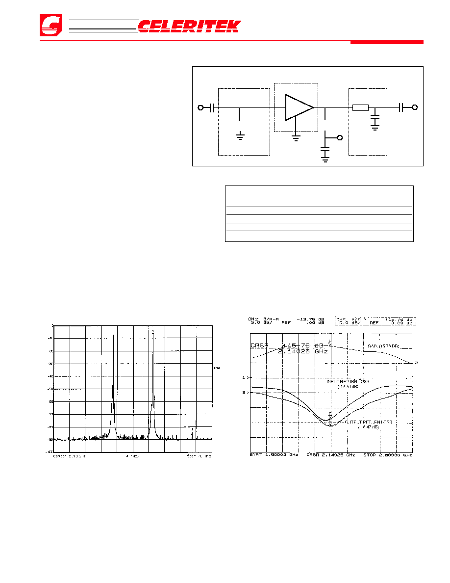
Application Circuit (2.1 GHz)
Typical Performance (50 Ohm System)
Frequency
2.1 GHz
Gain
15.8 dB
Input Return Loss
-14 dB
Output return Loss
-16.5 dB
OIP3
40 dBm
Noise Figure
2.95 dB
Bias
Vds = 5V, Id = 175 mA
Typical Performance
RF
OUT
uuuu
uuuu
C3
1.5 pF
C4
100 pF
L2
22 nH
Vcc
5V
C2
1.0 pF
L1
1.8 nH
RF
IN
2.1 GHz
CMM6004-AH
T1
50
33�
OUTPUT
MATCHING
NETWORK
INPUT MATCHING
NETWORK
Circuit Board Parts List
Part
Reference
Type
Designator
Description
Inductor
L1
0603, �0.3, 1.8 nH
Inductor
L2
0603, 22 nH
Capacitor
C1, C4
SMD 0805 NPO, 100 pF
Capacitor
C2
0603, 1 pF
Capacitor
C3
SMD 0603, 50V �0.1 pF 1.5 pF
C1
100 pF

3236 Scott Boulevard, Santa Clara, California 95054
Phone: (408) 986-5060
Fax: (408) 986-5095
CMM6004-AH
Advanced Product Information - February 2002
(4 of 6)
RF
OUT
uuuu
C4
100 pF
L1
6.8 nH
Vcc
5V
C3
1.0 pF
C2
3.9 pF
RF
IN
5.8 GHz
CMM6004-AH
T1
50
110�
T1
50
125�
Application Circuit (5.8 GHz)
Typical Performance
Gain vs Temperature @ 5.8 GHz
IP3 vs Temperature @ 5.8 GHz
Typical Performance (50 Ohm System)
Frequency
5.8 GHz
Gain
10.5 dB
Input Return Loss
-11.5 dB
Output Return Loss
-17.2 dB
OIP3
40 dBm
Noise FIgure
3.8 dB
Bias
Vds = 5V, Ids = 175 mA
IP3 measured with 2 tones at an output power of 5
dBm/tone separated by 10 MHz
Gain, Input Return Loss and Output Return Loss
vs Frequency
INPUT MATCHING
NETWORK
Circuit Board Parts List
Part
Reference
Type
Designator
Description
Inductor
L1
0603, 6.8 nH
Capacitor
C1, C4
SMD 0805 NPO, 100 pF
Capacitor
C2
SMD 0805, 3.9 pF
Capacitor
C3
0603, 1 pF
C1
100 pF

3236 Scott Boulevard
Santa Clara, California 95054
Phone: (408) 986-5060
Fax: (408) 986-5095
CMM6004-AH
Advanced Product Information - February 2002
(5 of 6)
Physical Dimensions
Mounting Recommendation
Dimensions in millimeters/inches
Board substrate:
RO-4003
Thickness = 31 mil
Ordering Information
The CMM6004-AHis available in a surface-mount LGA package and devices are available in tape and reel.
Part Number for Ordering
Package
CMM6004-AH
LGA surface-mount power package in tape and reel
PB-CMM6004-AH
Evaluation Board with SMA connectors for CMM6004-AH

3236 Scott Boulevard, Santa Clara, California 95054
Phone: (408) 986-5060
Fax: (408) 986-5095
CMM6004-AH
Advanced Product Information - February 2002
(6 of 6)
Celeritek reserves the right to make changes without further notice to any products herein. Celeritek makes no warranty, representation or guarantee regarding the
suitability of its products for any particular purpose, nor does Celeritek assume any liability arising out of the application or use of any product or circuit, and specifically
disclaims any and all liability, including without limitation consequential or incidental damages. "Typical" parameters can and do vary in different applications. All operating
parameters, including "Typicals" must be validated for each customer application by customer's technical experts. Celeritek does not convey any license under its patent
rights nor the rights of others. Celeritek products are not designed, intended, or authorized for use as components in systems intended for surgical implant into the body,
or other applications intended to support or sustain life, or for any other application in which the failure of the Celeritek product could create a situation where personal
injury or death may occur. Should Buyer purchase or use Celeritek products for any such unintended or unauthorized application, Buyer shall indemnify and hold Celeritek
and its officers, employees, subsidiaries, affiliates, and distributors harmless against all claims, costs, damages, and expenses, and reasonable attorney fees arising out
of, directly or indirectly, any claim of personal injury or death associated with such unintended or unauthorized use, even if such claim alleges that Celeritek was negligent
regarding the design or manufacture of the part. Celeritek is a registered trademark of Celeritek, Inc. Celeritek, Inc. is an Equal Opportunity/Affirmative Action Employer.
Notes