
General Description
The MAX6853 compact vacuum-fluorescent display
(VFD) controller provides microprocessors with the mul-
tiplex timing for 5 x 7 matrix VFD displays up to 96
characters and controls industry-standard, shift-regis-
ter, high-voltage grid/anode VFD tube drivers. The
device supports display tubes using either one or two
digits per grid, as well as universal displays. The
MAX6853 provides an internal crosspoint switch to
match any tube-driver shift-register grid/anode order,
and is compatible with both chip-in-glass and external
tube drivers. Hardware is included to simplify the gen-
eration of cathode bias and filament supplies and to pro-
vide up to five logic outputs, including a buzzer driver.
The MAX6853 includes an ASCII 104-character font,
multiplex scan circuitry, and static RAM that stores
digit, cursor, and annunciator data, as well as font data
for 24 user-definable characters. An internal 16-step
digital brightness control adjusts the display intensity.
The device also includes separate annunciator and cur-
sor control with automatic blinking, as well as a low-
power shutdown mode.
The MAX6853 provides timing to generate the PWM
waveforms to drive the tube filament from a DC supply.
The filament drive is synchronized to the display multi-
plexing to eliminate beat artifacts.
For an SPITM-compatible version, refer to the MAX6852
data sheet.
Applications
Features
o 400kbps 2-Wire I
2
C-Compatible Interface
o 2.7V to 3.6V Operation
o Controls Up to 96 5 x 7 Matrix Characters
o One Digit and Two Digits per Grid and Universal
Displays Supported
o 16-Step Digital Brightness Control
o Built-In ASCII 104-Character Font
o 24 User-Definable Characters
o Up to Four Annunciators per Grid with Automatic
Blinking Control
o Separate Cursor Control with Automatic Blinking
o Filament Drive Full-Bridge Waveform Synthesis
o Buzzer Tone Generator with Single-Ended or
Push-Pull Driver
o Up to Five General-Purpose Logic Outputs
o 9µA Low-Power Shutdown (Data Retained)
o 16-Pin QSOP Package
MAX6853
2-Wire Interfaced, 5
7 Matrix Vacuum-
Fluorescent Display Controller
________________________________________________________________ Maxim Integrated Products
1
Ordering Information
19-2673; Rev 0; 10/02
For pricing, delivery, and ordering information, please contact Maxim/Dallas Direct! at
1-888-629-4642, or visit Maxim's website at www.maxim-ic.com.
PART
TEMP RANGE
PIN-PACKAGE
MAX6853AEE
-40
°C to +125°C
16 QSOP
Display Modules
Retail POS Displays
Weight and Tare
Displays
Bar Graph Displays
Industrial Controllers
SPI is a trademark of Motorola, Inc.
MAX6853
VFCLK
VFDOUT
VFLOAD
VFBLANK
OSC2
SDA
V+
SCL
AD0
OSC1
SDA
SCL
MICROCONTROLLER
56pF
0.1
µF
GND
CHIP-ON-GLASS VFD
VFD SUPPLY VOLTAGE
10k
Typical Application Circuit
Pin Configuration and Functional Diagram appear at end of
data sheet.

MAX6853
2-Wire Interfaced, 5
7 Matrix Vacuum-
Fluorescent Display Controller
2
_______________________________________________________________________________________
ABSOLUTE MAXIMUM RATINGS
Stresses beyond those listed under "Absolute Maximum Ratings" may cause permanent damage to the device. These are stress ratings only, and functional
operation of the device at these or any other conditions beyond those indicated in the operational sections of the specifications is not implied. Exposure to
absolute maximum rating conditions for extended periods may affect device reliability.
Voltage (with respect to GND)
V+ .............................................................................-0.3V to +4V
AD0, SDA, SCL......................................................-0.3V to +5.5V
All Other Pins................................................-0.3V to (V+ + 0.3V)
Current
V+..................................................................................200mA
GND .............................................................................-200mA
PHASE1, PHASE2, PORT0, PORT1, PUMP................±150mA
VFCLK, VFDOUT, VFLOAD, VFBLANK ......................±150mA
SDA .................................................................................15mA
Continuous Power Dissipation (T
A
= +70°C)
16-Pin QSOP (derate at 8.34mW/°C above +70°C).....667mW
Operating Temperature Range (T
MIN
, T
MAX
)
MAX6853AEE................................................-40°C to +125°C
Junction Temperature ......................................................+150°C
Storage Temperature Range .............................-65°C to +150°C
Lead Temperature (soldering, 10s) .................................+300°C
DC ELECTRICAL CHARACTERISTICS
(Typical operating circuit, V+ = 2.7V to 3.6V, T
A
= T
MIN
to T
MAX
, unless otherwise noted.) (Note 1)
PARAMETER
SYMBOL
CONDITIONS
MIN
TYP
MAX
UNITS
Operating Supply Voltage
V+
2.7
3.6
V
T
A
= T
MIN
to
T
MAX
160
Shutdown Supply Current
I
SHDN
Shutdown mode, all digital
inputs at V+ or GND
T
A
= +25°C
9
20
µA
T
A
= T
MIN
to
T
MAX
3
Operating Supply Current
I+
OSC = 4MHz
VFLOAD, VFDOUT, VFCLK,
VFBLANK, loaded 100pF
T
A
= +25°C
1.65
2
mA
Master Clock Frequency (OSC
Internal Oscillator)
f
OSC
OSC1 fitted with C
OSC
= 56pF, OSC2 fitted
with R
OSC
= 10k
; see the Typical
Operating Circuit
4
MHz
Master Clock Frequency (OSC
External Oscillator)
OSC1 overdriven with external f
OSC
2
8
MHz
Dead-Clock Protection
Frequency
200
kHz
OSC High Time
t
CH
50
ns
OSC Low Time
t
CL
50
ns
Fast or Slow Segment Blink Duty
Cycle
(Note 2)
49.5
50.5
%
LOGIC INPUTS AND OUTPUTS
Input Leakage Current AD0,
SDA, SCL
I
IH
, I
IL
0.2
1
µA
Logic-High Input Voltage AD0,
SDA, SCL
V
IH
2.4
V
Logic-Low Input Voltage AD0,
SDA, SCL
V
IL
0.6
V
SDA Output Low Voltage
V
OLSDA
I
SINK
= 3mA
0.5
V
Input Capacitance
C
I
10
pF

MAX6853
2-Wire Interfaced, 5
7 Matrix Vacuum-
Fluorescent Display Controller
_______________________________________________________________________________________
3
PARAMETER
SYMBOL
CONDITIONS
MIN
TYP
MAX
UNITS
Output Rise and Fall Time
PHASE1, PHASE2, PORT0,
PORT1, PUMP, VFLOAD,
VFDOUT, VFCLK, VFBLANK
t
RFT
C
LOAD
= 100pF
25
ns
Output High-Voltage
PHASE1, PHASE2, PORT0,
PORT1, PUMP, VFLOAD,
VFDOUT, VFCLK, VFBLANK
V
OH
I
SOURCE
= 10mA
V + - 0.6
V
Output Low-Voltage
PHASE1, PHASE2, PORT0,
PORT1, PUMP, VFLOAD,
VFDOUT, VFCLK, VFBLANK
V
OL
I
SINK
= 10mA
0.4V
V
Output Short-Circuit Source
Current PHASE1, PHASE2,
PORT0, PORT1, PUMP, VFLOAD,
VFDOUT, VFCLK, VFBLANK
I
OHSC
Output programmed high, output short
circuit to GND (Note 2)
62
125
mA
Output Short-Circuit Sink Current
PHASE1, PHASE2, PORT0,
PORT1, PUMP, VFLOAD,
VFDOUT, VFCLK, VFBLANK
I
OLSC
Output programmed low, output short
circuit to V+ (Note 2)
72
125
mA
I
2
C TIMING CHARACTERISTICS (Figure 6)
Serial Clock Frequency
f
SCL
400
kHz
Bus Free Time Between a STOP
and a START Condition
t
BUF
1.3
µs
Hold Time (Repeated) START
Condition
t
HD
,
STA
0.6
µs
Repeated START Condition
Setup Time
t
SU
,
STA
0.6
µs
STOP Condition Setup Time
t
SU, STO
0.6
µs
Data Hold Time
t
HD, DAT
(Note 3)
0.9
µs
Data Setup Time
t
SU, DAT
100
ns
SCL Clock Low Period
t
LOW
1.3
µs
SCL Clock High Period
t
HIGH
0.6
µs
Rise Time of Both SDA and SCL
Signals, Receiving
t
R
(Notes 2, 4)
20 +
0.1C
B
300
ns
Fall Time of Both SDA and SCL
Signals, Receiving
t
F
(Notes 2, 4)
20 +
0.1C
B
300
ns
DC ELECTRICAL CHARACTERISTICS (continued)
(Typical operating circuit, V+ = 2.7V to 3.6V, T
A
= T
MIN
to T
MAX
, unless otherwise noted.) (Note 1)
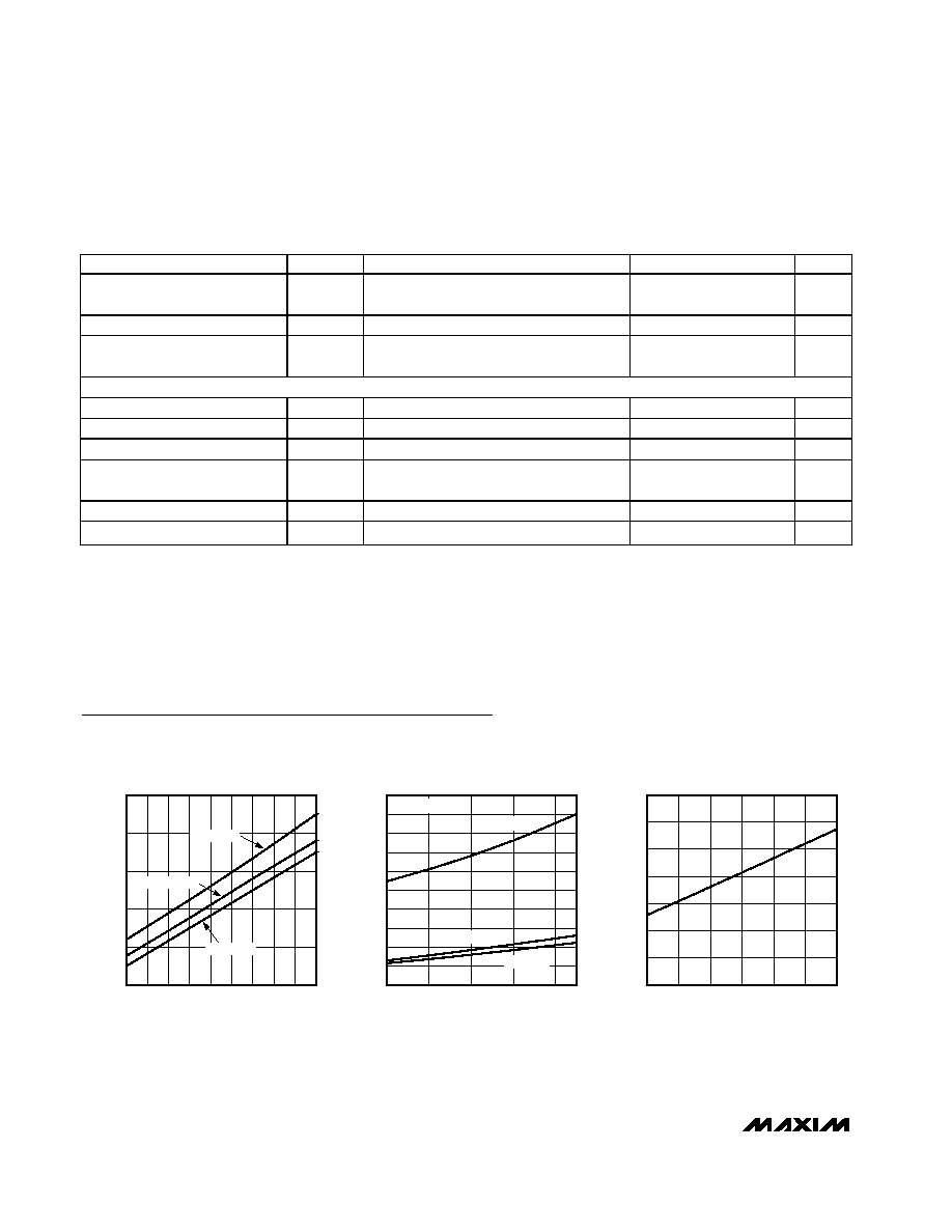
Typical Operating Characteristics
(Typical Operating Circuit, V+ = 3.3V, T
A
= +25°C, unless otherwise noted.)
SUPPLY CURRENT
vs. SUPPLY VOLTAGE
MAX6853 toc01
V
CC
(V)
I
CC
(mA)
3.5
3.4
3.3
3.2
3.1
3.0
2.9
2.8
1.3
1.5
1.7
1.9
2.1
1.1
2.7
3.6
T
A
= +125
°C
T
A
= +25
°C
T
A
= -40
°C
SHUTDOWN SUPPLY CURRENT
vs. SUPPLY VOLTAGE (OSC = 1)
MAX6853 toc02
V+ (V)
I SUPPLY
(
µ
A)
3.5
3.3
3.1
2.9
5
15
20
35
40
45
50
0
2.7
T
A
= -40
°C
OSC1 = 0
T
A
= +25
°C
T
A
= +125
°C
10
25
30
FREQUENCY (MHz)
7
6
5
4
3
200
400
600
800
1000
1200
1400
0
2
8
SHUTDOWN SUPPLY CURRENT
vs. EXTERNAL OSC FREQUENCY
MAX6853 toc03
I SUPPLY
(
µ
A)
MAX6853
2-Wire Interfaced, 5
7 Matrix Vacuum-
Fluorescent Display Controller
4
_______________________________________________________________________________________
PARAMETER
SYMBOL
CONDITIONS
MIN
TYP
MAX
UNITS
Fall Time of SDA Transmitting
t
F
(Notes 2, 5)
20 +
0.1C
B
250
ns
Pulse Width of Spike Suppressed
t
SP
(Note 6)
0
50
ns
Capacitive Load for Each
Bus Line
CB
(Note 2)
400
pF
VFD INTERFACE TIMING CHARACTERISTICS (Figure 14)
VFCLK Clock Period
t
VCP
(Note 2)
250
1050
ns
VFCLK Pulse Width High
t
VCH
(Note 2)
125
ns
VFCLK Pulse Width Low
t
VCL
(Note 2)
125
ns
VFCLK Rise to VFD Load Rise
Hold Time
t
VCSH
(Note 2)
19
µs
VFDOUT Setup Time
t
VDS
(Note 2)
50
ns
VFLOAD Pulse High
t
VCSW
(Note 2)
245
ns
DC ELECTRICAL CHARACTERISTICS (continued)
(Typical operating circuit, V+ = 2.7V to 3.6V, T
A
= T
MIN
to T
MAX
, unless otherwise noted.) (Note 1)
Note 1: All parameters tested at T
A
= +25°C. Specifications over temperature are guaranteed by design.
Note 2: Guaranteed by design.
Note 3: A master device must provide a hold time of at least 300ns for the SDA signal (referred to V
IL
of the SCL signal) in order to
bridge the undefined region of SCL's falling edge.
Note 4: C
B
= total capacitance of one bus line in pF. t
R
and t
F
measured between 0.3V+ and 0.7V+.
Note 5: I
SINK
6mA. C
B
= total capacitance of one bus line in pF. t
R
and t
F
measured between 0.3V+ and 0.7V+.
Note 6: Input filters on the SDA and SCL inputs suppress noise spikes less than 50ns.

MAX6853
2-Wire Interfaced, 5
7 Matrix Vacuum-
Fluorescent Display Controller
_______________________________________________________________________________________
5
80
60
40
20
0
100
OUTPUT LOW VOLTAGE vs. I
SINK
MAX6853 toc04
ISINK
(mA)
V
OL
(V)
0.2
0.6
0.8
1.4
1.6
1.8
2.0
0
T
A
= -40
°C
0.4
1.0
1.2
V+ = 3.3V
V+ = 3.6V
V+ = 2.7V
80
60
40
20
0
100
OUTPUT LOW VOLTAGE vs. I
SINK
MAX6853 toc05
ISINK
(mA)
V
OL
(V)
0.2
0.6
0.8
1.4
1.6
1.8
2.0
0
T
A
= +25
°C
0.4
1.0
1.2
V+ = 3.6V
V+ = 2.7V
V+ = 3.3V
80
60
40
20
0
100
OUTPUT LOW VOLTAGE vs. I
SINK
MAX6853 toc06
ISINK
(mA)
V
OL
(V)
0.2
0.6
0.8
1.4
1.6
1.8
2.0
0
T
A
= +125
°C
0.4
1.0
1.2
V+ = 3.6V
V+ = 2.7V
V+ = 3.3V
80
60
40
20
0
100
V
IN
-
V
OH
vs. I
SOURCE
MAX6853 toc07
ISOURCE
(mA)
V
OL
(V)
0.5
1.5
2.0
0
1.0
T
A
= -40
°C
V+ = 3.6V
V+ = 2.7V
V+ = 3.3V
80
60
40
20
0
100
V
IN
-
V
OH
vs. I
SOURCE
MAX6853 toc08
ISOURCE
(mA)
V
OL
(V)
0.2
0.6
0.8
1.4
1.6
1.8
2.0
0
T
A
= +25
°C
0.4
1.0
1.2
V+ = 3.6V
V+ = 2.7V
V+ = 3.3V
80
60
40
20
0
100
V
IN
-
V
OH
vs. I
SOURCE
MAX6853 toc09
ISOURCE
(mA)
V
OL
(V)
0.5
1.5
2.0
0
1.0
T
A
= +125
°C
V+ = 3.6V
V+ = 2.7V
V+ = 3.3V
Typical Operating Characteristics (continued)
(Typical Operating Circuit, V+ = 3.3V, T
A
= +25°C, unless otherwise noted.)
f
OSC
vs. TEMPERATURE
MAX6853 toc10
TEMPERATURE (
°C)
f
OSC
(MHz)
110
95
80
65
50
35
20
5
-10
-25
0.5
1.0
1.5
2.0
2.5
0
-40
125
V+ = 2.7V
V+ = 3.3V
V+ = 3.6V
DEAD-CLOCK OSC FREQUENCY
vs. TEMPERATURE
MAX6853 toc11
TEMPERATURE (
°C)
FREQUENCY (MHz)
110
95
80
65
50
35
20
5
-10
-25
-40
125
0.02
0.04
0.06
0.08
0.10
0.12
0.14
0.16
0.18
0
V+ = 2.7V
V+ = 3.6V
V+ = 3.3V