Äîêóìåíòàöèÿ è îïèñàíèÿ www.docs.chipfind.ru
________________General Description
The MAX3766 is a complete, easy-to-program laser
driver for fiber optic LAN transmitters, optimized for
operation at 622Mbps. It includes a laser modulator,
automatic power control (APC), and a failure indicator
with latched shutdown.
Laser modulation current can be programmed up to
60mA at 622Mbps. A programmable modulation tem-
perature coefficient can be used to keep the transmit-
ted extinction ratio nearly constant over a wide
temperature range. The modulator operates at data
rates up to 1.25Gbps at reduced modulation current.
APC circuitry uses feedback from the laser's monitor
photodiode to adjust the laser bias current, producing
constant output power regardless of laser temperature
or age. The MAX3766 supports laser bias currents up
to 80mA.
The MAX3766 provides extensive laser safety features,
including a failure indicator with latched shutdown and
a smooth start-up bias generator. These features help
ensure that the transmitter output does not reach haz-
ardous levels. The MAX3766 is available in a compact
20-pin QSOP and dice.
________________________Applications
622Mbps ATM Transmitters
1.25Gbps Fiber Optic LAN Transmitters
1.25Gbps Ethernet Transmitters
____________________________Features
o
60mA Modulation Current
o
80mA Bias Current
o
200ps Edge Speed
o
Modulation-Current Temperature Compensation
o
Automatic Power Control
o
Laser-Fail Indicator with Latched Shutdown
o
Smooth Laser Start-Up
MAX3766
622Mbps LAN/WAN Laser Driver with
Automatic Power Control and Safety Shutdown
________________________________________________________________
Maxim Integrated Products
1
19-1249; Rev 0b; 10/97
PART
MAX3766EEP
MAX3766E/D
-40°C to +85°C
-40°C to +85°C
TEMP. RANGE
PIN-PACKAGE
20 QSOP
Dice*
EVALUATION KIT
AVAILABLE
Ordering Information
*
Dice are designed to operate over this range, but are tested and
guaranteed at T
A
= +25°C only. Contact factory for availability.
Typical Application Circuits appear at end of data sheet.
Pin Configuration
20
19
18
17
16
15
14
13
1
2
3
4
5
6
7
8
REF1
POWERSET
MD
GNDOUT
MOD
REF2
TC
BIASMAX
TOP VIEW
BIAS
OUT+
OUT-
V
CCOUT
GND
IN+
IN-
GND
12
11
9
10
FAIL
SAFETY
ENABLE
V
CC
MAX3766
QSOP
For free samples & the latest literature: http://www.maxim-ic.com, or phone 1-800-998-8800.
For small orders, phone 408-737-7600 ext. 3468.
MAX3766
622Mbps LAN/WAN Laser Driver with
Automatic Power Control and Safety Shutdown
2
_______________________________________________________________________________________
ABSOLUTE MAXIMUM RATINGS
ELECTRICAL CHARACTERISTICS
Stresses beyond those listed under "Absolute Maximum Ratings" may cause permanent damage to the device. These are stress ratings only, and functional
operation of the device at these or any other conditions beyond those indicated in the operational sections of the specifications is not implied. Exposure to
absolute maximum rating conditions for extended periods may affect device reliability.
Supply Voltage, V
CC
, V
CCOUT
.................................-0.5V to 7.0V
Voltage at IN+, IN-, ENABLE,
SAFETY, FAIL ...........................................-0.5V to (V
CC
+ 0.5V)
Voltage at MOD, BIASMAX, POWERSET, TC ..........-0.5V to 4.0V
Current out of REF1, REF2 .................................-0.1mA to 10mA
Current into OUT+, OUT- ....................................-5mA to 100mA
Current into BIAS.................................................-5mA to 130mA
Current into MD .......................................................-5mA to 5mA
Current into FAIL ...................................................-5mA to 30mA
Current into SAFETY..............................................-5mA to 10mA
Continuous Power Dissipation (T
A
= +85°C)
QSOP (derate 9.1mW/°C above +85°C) .......................590mW
Operating Junction Temperature Range ...........-40°C to +150°C
Processing Temperature (dice) .......................................+400°C
Storage Temperature Range .............................-55°C to +150°C
Lead Temperature (soldering, 10sec) .............................+300°C
CONDITIONS
UNITS
MIN
TYP
MAX
PARAMETER
V
4.5
5.0
5.5
Supply Voltage, V
CC
(Note 1)
°C
-40
25
85
Ambient Operating Temperature
Referenced to V
CC
V
-1.4
-1.3
-1.19
Input Common-Mode Voltage
V
0.8
Enable Input Low
V
IN+
- V
IN-
, common-mode input =
V
CC
- 1.3V, Figure 1
V
2.0
Enable Input High
mV
500
1000
1800
Differential Input Signal Amplitude
V
V
CC
- 2.5
Voltage at BIAS
While using APC
%
50
Data Duty Cycle
Gbps
DC to 1.25
Data Rate
V
V
CC
- 2.5
Voltage at OUT+, OUT-
Not tested
mA/mA
0.001 to 0.1
Laser to PIN Coupling
R
F AIL
= 5.1k
V
4.3
FAIL Output High
(Note 3)
mA
0.5
80
Bias-Current Range
I
CC
(Note 2)
I
MD
> 15µA, R
F AIL
= 5.1k
V
0.33
0.44
FAIL Output Low
mA
21
25
32
Supply Current
µA
0.1
10
Bias Current when Driver is
Disabled or Shut Down
Input data low (Note 2)
µA
1
200
Modulation Current
Input data high (Note 3)
mA
2
60
Modulation-Current Programmable
Range
R
TC
= 0
ppm/°C
-50
Minimum Modulation-Current
Temperature Compensation
µA
10
Modulation Current when Driver is
Disabled or Shut Down
All DC testing uses 5.1k
load
k
2.7 to 20
FAIL Load
R
TC
= open
ppm/°C
5600
Maximum Modulation-Current
Temperature Compensation
RECOMMENDED OPERATING CONDITIONS
DC PARAMETERS
MAX3766
622Mbps LAN/WAN Laser Driver with
Automatic Power Control and Safety Shutdown
_______________________________________________________________________________________
3
ELECTRICAL CHARACTERISTICS (continued)
Note 1:
Dice are tested at room temperature only (T
A
= +25°C).
Note 2:
V
CC
= +5.5V, R
BIASMAX
= 887
, R
MOD
= 887
, R
POWERSET
= 287
, R
TC
= 0
, V
BIAS
= V
OUT+
= V
OUT-
= 3.0V. Supply
current excludes I
BIAS
, I
OUT+
, I
OUT-
, and I
FAIL
.
Note 3:
Total output current must be reduced at high temperatures with packaged product to maintain maximum junction
temperature of T
j
= +150°C. See the
Design Procedure section.
Note 4:
All AC parameters are measured with a 25
load. I
MOD
is the AC current amplitude at either OUT pin. The AC voltage at
OUT is greater than V
CC
- 2.5V.
Note 5:
Pulse-width distortion is measured at the 50% crossing point. Data input is a 155MHz square wave, with t
R
300ps.
Note 6:
AC specifications are guaranteed by design and characterization.
V
CC
- V
MD
V
1.5
2.1
2.3
Monitor-Diode Bias Voltage
Referenced to V
CC
V
-2.8
Lower MD Voltage for Failure
Referenced to V
CC
V
-1.2
Upper MD Voltage for Failure
Referenced to nominal V
REF1
V
0.5
REF1 Voltage for Failure
T
A
= +25°C, V
REF2
V
2.1
2.4
2.7
REF2 Reference Voltage
Width of operating window, centered at
nominal V
MD
T
A
= +25°C, V
REF1
V
CONDITIONS
2.8
3.1
3.4
REF1 Reference Voltage
mV
300
Range of MD for No Failure
I
MOD
= 60mA
210
400
Output Edge Speed (20% to 80%)
I
MOD
= 10mA
ps
125
250
I
MOD
= 30mA
160
300
I
MOD
= 30mA
%
10
Output Aberrations
µA
15
2000
Monitor-Diode Current
Programmable Range
UNITS
MIN
TYP
MAX
PARAMETER
I
MOD
= 60mA
5
80
I
MOD
= 30mA
20
80
I
MOD
= 10mA
ps
80
120
Pulse-Width Distortion
RMS, T
A
= +25°C, V
CC
= +5V, I
MOD
= 30mA
ps
2
3
Random Jitter
AC PARAMETERS
(Notes 4, 5, and 6)
MAX3766
622Mbps LAN/WAN Laser Driver with
Automatic Power Control and Safety Shutdown
4
_______________________________________________________________________________________
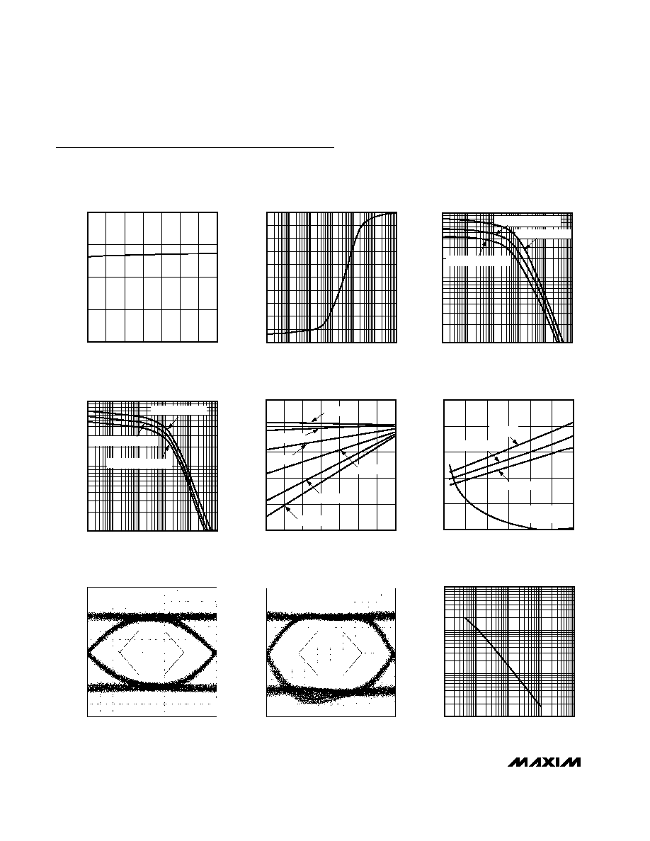
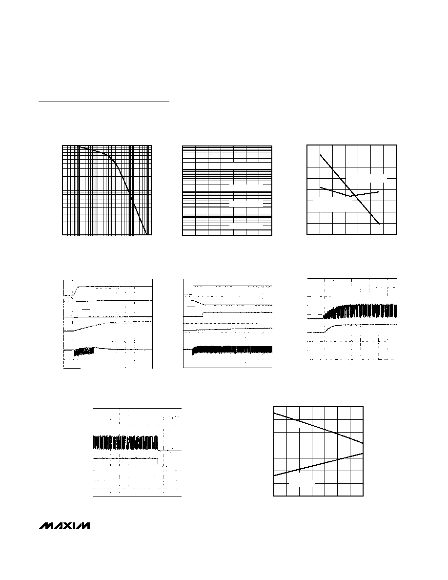
Typical Operating Characteristics
(Typical Operating Characteristics are measured on the MAX3766 evaluation kit, V
CC
= +5.0V, T
A
= +25°C, unless otherwise noted.)
0
20
10
30
40
-40
0
20
-20
40
60
80
100
SUPPLY CURRENT vs. TEMPERATURE
(EXCLUDES OUTPUT CURRENTS AND I
FAIL
)
MAX3766-01
AMBIENT TEMPERATURE (°C)
SUPPLY CURRENT (mA)
6000
4000
1
1k
10
100
10k
100k
1M
MODULATION CURRENT TEMPCO
vs. R
TC
MAX3766-02
R
TC
(
)
TEMPCO (ppm/°C)
0
2000
100
1
1
1k
10
100
10k
100k
DIE MODULATION CURRENT vs. R
MOD
(T
J
= +25°C)
MAX3766-03
R
MOD
(
)
LASER MODULATION CURRENT (mAp-p)
10
TEMPCO = 0ppm/°C
TEMPCO = 5600ppm/°C
TEMPCO = 3000ppm/°C
100
1
1
1k
10
100
10k
100k
MODULATION CURRENT vs. R
MOD
(20 QSOP, T
A
= +25°C)
MAX3766-04
R
MOD
(
)
LASER MODULATION CURRENT (mAp-p)
10
TEMPCO = 0ppm/°C
TEMPCO = 3000ppm/°C
TEMPCO = 5600ppm/°C
125
µ
W/div
161ps/div
EYE DIAGRAM
(622Mbps, 1300nm LASER, 470MHz FILTER)
MAX3766-07
2
31
- 1 PRBS
20
30
40
50
60
70
-40
0
20
-20
40
60
80
100
MODULATION CURRENT
vs. TEMPERATURE
MAX3766-05
AMBIENT TEMPERATURE (°C)
MODULATION CURRENT (mAp-p)
R
TC
= 100
R
TC
= 330
R
TC
= 1k
R
TC
= 3.3k
R
TC
= 10k
R
TC
= 100k
0
50
100
150
200
250
0
30
10
20
40
50
60
MODULATION EDGE SPEED AND
PWD vs. AMPLITUDE
MAX3766-06
MODULATION CURRENT (mAp-p)
20% TO 80% EDGE SPEED (ps)
T
A
= +85°C
T
A
= +25°C
T
A
= -40°C
PULSE-WIDTH
DISTORTION (ps)
60mA/div
81ps/div
EYE DIAGRAM
(1.244Gbps, 25
LOAD, I
MOD
= 60mA)
MAX3766-08
2
31
- 1 PRBS
0.01
1
0.1
10
100
1000
MONITOR CURRENT vs. R
POWERSET
MAX3766-09
R
POWERSET
(k
)
MD CURRENT (mA)
0.1
1
10
MAX3766
622Mbps LAN/WAN Laser Driver with
Automatic Power Control and Safety Shutdown
_______________________________________________________________________________________
5
100
1
1k
10
100
10k
100k
BIAS CURRENT vs. R
BIASMAX
(NO APC, OPEN-LOOP CONFIGURATION)
MAX3766-10
R
BIASMAX
(
)
I
BIAS
(mA)
1
10
10
0.001
-40
-20
0
20
40
60
80
100
MONITOR CURRENT vs. TEMPERATURE
0.01
MAX3766-11
AMBIENT TEMPERATURE (°C)
I
MD
(mA)
0.1
1
NOMINAL = 1mA
NOMINAL = 200
µ
A
NOMINAL = 20
µ
A
NOMINAL = 2
µ
A
100
260
240
220
200
180
160
140
120
DATA-DEPENDENT JITTER
vs. TEMPERATURE (CMD = 0.1
µ
F)
MAX3766-12
AMBIENT TEMPERATURE (°C)
DDJ (ps)
-40
-20
0
20
40
60
80
100
2
13
PRBS PATTERN
72 CONSECUTIVE ZEROS
2
23
- 1 PRBS PATTERN
10
µ
s/div
UNSUCCESSFUL STARTUP
MAX3766-13
V
ENABLE
V
MD
V
SAFETY
(
= 30
µ
s)
FAIL
DATA OUT (AC COUPLED)
5
µ
s/div
100
µ
W/
div
ABRUPT SHUTDOWN
MAX3766-16
OPTICAL OUTPUT WITH DATA ON
OPTICAL OUTPUT WITH DATA OFF
50
µ
s/div
SUCCESSFUL STARTUP
MAX3766-14
V
ENABLE
V
MD
FAIL
V
SAFETY
(
= 1500
µ
s)
DATA OUT (AC COUPLED)
5
µ
s/div
100
µ
W/
div
SMOOTH STARTUP
MAX3766-15
OPTICAL OUTPUT WITH DATA ON
OPTICAL OUTPUT WITH DATA OFF
2.00
2.80
2.60
2.40
2.20
3.20
3.00
3.40
-45
-5
20
-25
40
60
80
100
REFERENCE VOLTAGE
vs. TEMPERATURE
MAX3766-17
AMBIENT TEMPERATURE (°C)
VOLTAGE (V)
R
TC
= OPEN
V
REF1
V
REF2
Typical Operating Characteristics (continued)
(Typical Operating Characteristics are measured on the MAX3766 evaluation kit, V
CC
= +5.0V, T
A
= +25°C, unless otherwise noted.)