
General Description
The MAX2605MAX2609 evaluation kits (EV kits) simplify
evaluation of this family of voltage-controlled oscillators
(VCOs). These kits enable testing of the devices' per-
formance and require no additional support circuitry.
Both signal outputs use SMA connectors to facilitate
connection to RF test equipment.
These EV kits are fully assembled and tested. Their oscil-
lation frequencies are set to approximately the midrange
of the respective VCOs.
Features
o Easy Evaluation
o Complete, Tunable VCO Test Board with Tank
Circuit
o Low Phase Noise
o Fully Assembled and Tested
Evaluate: MAX2605MAX2609
MAX2605MAX2609 Evaluation Kits
________________________________________________________________ Maxim Integrated Products
1
19-1673 Rev 0; 9/00
PART
MAX2605EVKIT
MAX2606EVKIT
-40°C to +85°C
-40°C to +85°C
TEMP. RANGE
IC PACKAGE
6 SOT23-6
6 SOT23-6
Ordering Information
MAX2607EVKIT
MAX2608EVKIT
-40°C to +85°C
-40°C to +85°C
6 SOT23-6
6 SOT23-6
SUPPLIER
PHONE
FAX
AVX
803-946-0690
803-626-3123
Coilcraft
847-639-6400
847-639-1469
EFJohnson
402-474-4800
402-474-4858
WEBSITE
avx-corp.com
coilcraft.com
efjohnson.com
Component Suppliers
MAX2609EVKIT
-40°C to +85°C
6 SOT23-6
Murata
814-237-1431
814-238-0490
murata.com
For free samples and the latest literature, visit www.maxim-ic.com or phone 1-800-998-8800.
For small orders, phone 1-800-835-8769.
D ESIG N A T IO N
QTY
DESCRIPTION
C1, C4
2
1000pF
±5% ceramic capacitors
(0603)
Murata GRM39COH102J025A or
AVX 06035A102JAT2A
C2, C3
2
12pF
±5% ceramic capacitors
(0603)
Murata GRM39COG120J050A
C5
1
10
µF ±10%, 16V tantalum cap aci tor
AVX TAJC106K016
R1
1
270
±5% resistor (0603)
R2, R3
2
Not installed
R4
1
10
±5% resistor (0603)
L1, L2
2
Not installed
L4, L5
2
680nH inductors
Coilcraft 1008CS-681XJBC
L3
1
1.2
µH inductor
Coilcraft 1206CS-122XJBC
U1
1
MAX2605EUT
J1, J2
2
SMA connectors (edge mount)
EFJohnson 142-0701-801 or
Digi-Key J502-ND
VCC,GND,
TUNE
6
Test points
Digi-Key 5000K-ND
None
1
MAX2605/6/7 EV kit circuit board
None
1
MAX2605MAX2609 data sheet
MAX2606 Component List
D ESIGNA T ION
QTY
DESCRIPTION
C1, C4
2
1000pF
±5% ceramic capacitors
(0603)
Murata GRM39COH102J025A or
AVX 06035A102JAT2A
C2, C3
2
4.7pF
±0.25% ceramic
capacitors (0603)
Murata GRM39COG4R7C050A
C5
1
10
µF ±10%, 16V tantalum cap aci tor
AVX TAJC106K016
R1
1
270
±5% resistor (0603)
R2, R3
2
Not installed
R4
1
10
±5% resistor (0603)
L1, L2
2
Not installed
L3
1
270nH
±2% inductor
Coilcraft 1008CS-271XJBC
L4, L5
2
330nH inductor
Coilcraft 1008CS-331XJBC
U1
1
MAX2606EUT
J1, J2
2
SMA connectors (edge mount)
EFJohnson 142-0701-801 or
Digi-Key J502-ND
VCC,GND,
TUNE
6
Test points
None
1
MAX2605/6/7 EV kit circuit board
None
1
MAX2605MAX2609 data sheet
MAX2605 Component List

Evaluate: MAX2605MAX2609
MAX2605MAX2609 Evaluation Kits
2
_______________________________________________________________________________________
Quick Start
The MAX2605MAX2609 evaluation kits are fully
assembled and factory tested. Follow the instructions in
the Connections and Setup section for proper device
evaluation.
Test Equipment Required
· Low-noise power supplies (these are recommended
for oscillator noise measurement). Noise or ripple will
frequency-modulate the oscillator and cause spectral
spreading. Batteries can be used in place of power
supplies, if necessary.
Use a DC power supply capable of supplying
+2.7V to +5.5V. Alternatively, use two or three 1.5V
batteries.
Use a DC power supply capable of supplying
+0.4V to +2.4V, continuously variable, for TUNE.
Alternatively, use two 1.5V batteries with a resistive
voltage divider or potentiometer.
· An RF spectrum analyzer that covers the operating
frequency range of the MAX2605MAX2609
· A 50
coaxial cable with SMA connectors
· An ammeter (optional)
Connections and Setup
1) Connect a DC supply (preset to +3V) to the V
CC
and
GND terminals (through an ammeter, if desired) on
the EV kit.
2) Turn on the DC supply. If used, the ammeter reading
MAX2607 Component List
D ESIG N A T IO N
QTY
DESCRIPTION
C1, C4
2
1000pF
±5% ceramic capacitors
(0603)
Murata GRM39COH102J025A or
AVX 06035A102JAT2A
C2, C3
2
3pF
±0.25% ceramic capacitors
(0603)
Murata GRM39COG030C050A
C5
1
10
µF ±10%, 16V tantalum cap aci tor
AVX TAJC106K016
R1
1
270
±5% resistor (0603)
R2, R3
2
Not installed
R4
1
10
±5% resistor (0603)
L1, L2
2
Not installed
L3
1
68nH
±2% inductor
Coilcraft 1008CS-680XJBC
L4, L5
2
120nH inductors
Coilcraft 1008CS-121XJBC
U1
1
MAX2607EUT
J1, J2
2
SMA connectors (edge mount)
EFJohnson 142-0701-801 or
Digi-Key J502-ND
VCC,GND,
TUNE
6
Test points
None
1
MAX2605/6/7 EV kit circuit board
None
1
MAX2605MAX2609 data sheet
MAX2608 Component List
D ESIG N A T IO N
QTY
DESCRIPTION
C1
1
1000pF
±5% ceramic capacitor
(0603)
Murata GRM39COH102J025A or
AVX 06035A102JAT2A
C2, C3
2
1pF
±0.25% ceramic capacitors
(0603)
Murata GRM39COG010C050A
C4, C6
2
100pF
±5% ceramic capacitors
(0603)
Murata GRM39COG101J050A
C5
1
10
µF ±10%, 16V tantalum cap aci tor
AVX TAJC106K016
R1
1
270
±5% resistor (0603)
R2, R3
2
Not installed
R4
1
10
±5% resistor (0603)
L1
1
22nH
±2% inductor
Coilcraft 0805CS-220XGBC
L4, L5
2
68nH
±2% inductors
Coilcraft 0805CS-680XJBC
U1
1
MAX2608EUT
J1, J2
2
SMA connectors (edge mount)
EFJohnson 142-0701-801 or
Digi-Key J502-ND
VCC,GND,
TUNE
6
Test points
Digi-Key 5000K-ND
None
1
MAX2608/9 EV kit circuit board
None
1
MAX2605MAX2609 data sheet

Evaluate: MAX2605MAX2609
MAX2605MAX2609 Evaluation Kits
_______________________________________________________________________________________
3
approximates the typical operating current specified
in the MAX2605MAX2609 data sheet.
3) Connect the VCO output (OUT+ or OUT-) to a spec-
trum analyzer with a 50
coaxial cable.
4) Apply a positive variable DC voltage between 0.4V
and 2.4V to TUNE.
5) Check the tuning bandwidth on the spectrum analyz-
er by varying the tuning voltage (+0.4V to +2.4V).
Layout Considerations
The EV kit PC board can serve as a guide for laying out
a board using the MAX2605MAX2609. Generally, the
VCC pin on the PC board should have a decoupling
capacitor placed close to the IC. This minimizes noise
coupling from the supply. Also, place the VCO as far
away as possible from the noisy section of a larger sys-
tem, such as a switching regulator or digital circuits.
The VCO's performance is strongly dependent on the
availability of the external tuning inductor. For best per-
formance, use high-Q components and choose their val-
ues carefully. To minimize the effects of parasitic ele-
ments, which degrade circuit performance, place the
tuning inductor and C
BYP
close to the VCO. For higher-
frequency versions, include the parasitic PC board
inductance and capacitance when calculating the
oscillation frequency. In addition, remove the ground
plane around and under the tuning inductor to minimize
the effect of parasitic capacitance.
Noise on TUNE translates into FM noise on the outputs;
therefore, keep the trace between TUNE and the control
circuitry as short as possible. If necessary, use an RC
filter to further suppress noise, as done on the EV kits.
MAX2609 Component List
D ESIG N A T IO N
QTY
DESCRIPTION
C1
1
1000pF
±5% ceramic capacitors
(0603)
Murata GRM39COH102J025A or
AVX 06035A102JAT2A
C2, C3
2
1pF
±0.25% ceramic capacitors
(0603)
Murata GRM39COG010C050A
C4, C6
2
100pF
±5% ceramic capacitors
(0603)
Murata GRM39COG101J050A
C5
1
10
µF ±10%, 16V tantalum cap aci tor
AVX TAJC106K016
R1
1
270
±5% resistor (0603)
R2, R3
2
Not installed
R4
1
10
±5% resistor (0603)
L1
1
8.2nH
±2% inductor
Coilcraft 0805CS-080XGBC
L4, L5
2
27nH
±2% inductors
Coilcraft 0805CS-270XJBC
U1
1
MAX2609EUT
J1, J2
2
SMA connectors (edge mount)
EFJohnson 142-0701-801 or
Digi-Key J502-ND
VCC,GND,
TUNE
6
Test points
Digi-Key 5000K-ND
None
1
MAX2608/9 EV kit circuit board
None
1
MAX2605MAX2609 data sheet

Evaluate: MAX2605MAX2609
MAX2605MAX2609 Evaluation Kits
4
_______________________________________________________________________________________
Figure 2. MAX2608/MAX2609 EV Kits Schematic
GND
+
6
5
4
1
2
3
TUNE
TUNE
OUT-
GND
U1
V
CC
IND
OUT+
C1
1000pF
R1
270
L1
OUT-
SMA
OUT+
SMA
C5
10V
10
µF
C4
100pF
C6
100pF
C3
C2
VCC
MAX2608
MAX2609
R4
10
L4
R3
OPEN
L5
R2
OPEN
Figure 1. MAX2605/MAX2606/MAX2607 EV Kits Schematic
GND
+
6
5
4
1
2
3
TUNE
TUNE
OUT-
GND
U1
V
CC
IND
OUT+
C1
1000pF
R1
270
L4
R3
OPEN
L5
R2
OPEN
L3
L2
OPEN
L1
OPEN
OUT-
SMA
OUT+
SMA
C5
10V
10
µF
C4
1000pF
C3
C2
VCC
R4
10
MAX2605
MAX2606
MAX2607
Evaluate: MAX2605MAX2609
MAX2605MAX2609 Evaluation Kits
_______________________________________________________________________________________
5
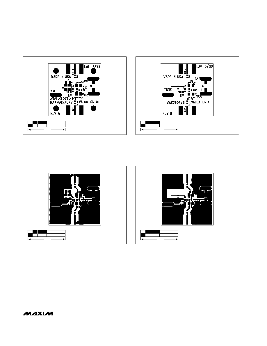
Figure 3. MAX2605/MAX2606/MAX2607 EV Kits Component
Placement Guide--Top Silk Screen
1.0"
Figure 4. MAX2608/MAX2609 EV Kits Component Placement
Guide--Top Silk Screen
1.0"
Figure 5. MAX2605/MAX2606/MAX2607 EV Kits PC Board
Layout--Component Side
1.0"
Figure 6. MAX2608/MAX2609 EV Kits PC Board Layout--
Component Side
1.0"

Maxim cannot assume responsibility for use of any circuitry other than circuitry entirely embodied in a Maxim product. No circuit patent licenses are
implied. Maxim reserves the right to change the circuitry and specifications without notice at any time.
6 _____________________Maxim Integrated Products, 120 San Gabriel Drive, Sunnyvale, CA 94086 408-737-7600
© 2000 Maxim Integrated Products
Printed USA
is a registered trademark of Maxim Integrated Products.
Evaluate: MAX2605MAX2609
MAX2605MAX2609 Evaluation Kits
Figure 7. MAX2605/MAX2606/MAX2607/MAX2608/MAX2609
EV Kits PC Board Layout--Ground Plane
1.0"