
General Description
The MAX1533/MAX1537 are dual step-down, switch-
mode power-supply (SMPS) controllers with synchro-
nous rectification, intended for main 5V/3.3V power
generation in battery-powered systems. Fixed-frequen-
cy operation with optimal interleaving minimizes input
ripple current from the lowest input voltages up to the
26V maximum input. Optimal 40/60 interleaving allows
the input voltage to go down to 8.3V before duty-cycle
overlap occurs, compared to 180
° out-of-phase regula-
tors where the duty-cycle overlap occurs when the
input drops below 10V. Output current sensing pro-
vides accurate current limit using a sense resistor.
Alternatively, power dissipation can be reduced using
lossless inductor current sensing.
Internal 5V and 3.3V linear regulators power the
MAX1533/MAX1537 and their gate drivers, as well as
external keep-alive loads, up to a total of 100mA. When
the main PWM regulators are in regulation, automatic
bootstrap switches bypass the internal linear regulators,
providing currents up to 200mA from each linear output.
An additional 5V to 23V adjustable internal 150mA linear
regulator is typically used with a secondary winding to
provide a 12V supply.
The MAX1533/MAX1537 include on-board power-up
sequencing, a power-good (PGOOD) output, digital
soft-start, and internal soft-shutdown output discharge
that prevents negative voltages on shutdown. The
MAX1533 is available in a 32-pin 5mm x 5mm thin QFN
package, and the MAX1537 is available in a 36-pin
6mm x 6mm thin QFN package. The exposed backside
pad improves thermal characteristics for demanding
linear keep-alive applications.
Applications
2 to 4 Li+ Cells Battery-Powered Devices
Notebook and Subnotebook Computers
PDAs and Mobile Communicators
Features
Fixed-Frequency, Current-Mode Control
40/60 Optimal Interleaving
Accurate Differential Current-Sense Inputs
Internal 5V and 3.3V Linear Regulators with
100mA Load Capability
Auxiliary 12V or Adjustable 150mA Linear
Regulator (MAX1537 Only)
Dual-ModeTM Feedback--3.3V/5V Fixed or
Adjustable Output (Dual Mode) Voltages
200kHz/300kHz/500kHz Switching Frequency
Versatile Power-Up Sequencing
Adjustable Overvoltage and Undervoltage
Protection
6V to 26V Input Range
2V ±0.75% Reference Output
Power-Good Output
Soft-Shutdown
5µA (typ) Shutdown Current
MAX1533/MAX1537
High-Efficiency, 5x Output, Main Power-Supply
Controllers for Notebook Computers
________________________________________________________________ Maxim Integrated Products
1
32
31
30
29
28
27
26
9
10
11
12
13
14
15
18
19
20
21
22
23
24
7
6
5
4
3
2
1
MAX1533
THIN QFN
5mm x 5mm
TOP VIEW
ON3
ON5
FSEL
ILIM3
ILIM5
REF
GND
8
V
CC
SHDN
DH5
BST5
LX5
IN
CSH5
25
CSL5
FB5
LDO5
DL5
PGND
DL3
LDO3
FB3
17
CSL3
OVP
LX3
16
CSH3
BST3
DH3
UVP
PGOOD
PGDL
Y
SKIP
Pin Configurations
Ordering Information
PART
TEMP RANGE
PIN-PACKAGE
MAX1533ETJ
-40°C to +85°C 32 Thin QFN 5mm x 5mm
MAX1533ETJ+
-40°C to +85°C 32 Thin QFN 5mm x 5mm
MAX1537ETX
-40°C to +85°C 36 Thin QFN 6mm x 6mm
MAX1537ETX+
-40°C to +85°C 36 Thin QFN 6mm x 6mm
19-3501; Rev 0; 11/04
For pricing, delivery, and ordering information, please contact Maxim/Dallas Direct! at
1-888-629-4642, or visit Maxim's website at www.maxim-ic.com.
EVALUATION KIT
AVAILABLE
Dual Mode is a trademark of Maxim Integrated Products, Inc.
Pin Configurations continued at end of data sheet.
+Denotes lead-free package.
MAX1533/MAX1537
High-Efficiency, 5x Output, Main Power-Supply
Controllers for Notebook Computers
2
_______________________________________________________________________________________
ABSOLUTE MAXIMUM RATINGS
ELECTRICAL CHARACTERISTICS
(Circuit of Figure 1, V
IN
= 12V, both SMPS enabled, V
CC
= 5V, FSEL = REF, SKIP = GND, V
ILIM_
= V
LDO5
, V
INA
= 15V, V
LDOA
= 12V,
I
LDO5
= I
LDO3
= I
LDOA
= no load, T
A
= 0°C to +85°C, unless otherwise noted. Typical values are at T
A
= +25°C.)
Stresses beyond those listed under "Absolute Maximum Ratings" may cause permanent damage to the device. These are stress ratings only, and functional
operation of the device at these or any other conditions beyond those indicated in the operational sections of the specifications is not implied. Exposure to
absolute maximum rating conditions for extended periods may affect device reliability.
IN, SHDN, INA, LDOA to GND ...............................-0.3V to +30V
GND to PGND .......................................................-0.3V to +0.3V
LDO5, LDO3, V
CC
to GND .......................................-0.3V to +6V
ILIM3, ILIM5, PGDLY to GND...................................-0.3V to +6V
CSL3, CSH3, CSL5, CSH5 to GND ..........................-0.3V to +6V
ON3, ON5, FB3, FB5 to GND ..................................-0.3V to +6V
SKIP, OVP, UVP to GND...........................................-0.3V to +6V
PGOOD, FSEL, ADJA, ONA to GND ........................-0.3V to +6V
REF to GND ................................................-0.3V to (V
CC
+ 0.3V)
DL3, DL5 to PGND..................................-0.3V to (V
LDO5
+ 0.3V)
BST3, BST5 to PGND .............................................-0.3V to +36V
LX3 to BST3..............................................................-6V to +0.3V
DH3 to LX3 ..............................................-0.3V to (V
BST3
+ 0.3V)
LX5 to BST5..............................................................-6V to +0.3V
DH5 to LX5 ..............................................-0.3V to (V
BST5
+ 0.3V)
LDO3, LDO5 Short Circuit to GND .............................Momentary
REF Short Circuit to GND ...........................................Momentary
INA Shunt Current.............................................................+15mA
Continuous Power Dissipation (T
A
= +70°C)
32-Pin TQFN (derate 21.3mW/°C above +70°C) .......1702mW
36-Pin TQFN (derate 26.3mW/°C above +70°C) .......2105mW
Operating Temperature Range ...........................-40°C to +85°C
Junction Temperature ......................................................+150°C
Storage Temperature Range .............................-65°C to +150°C
Lead Temperature (soldering, 10s) .................................+300°C
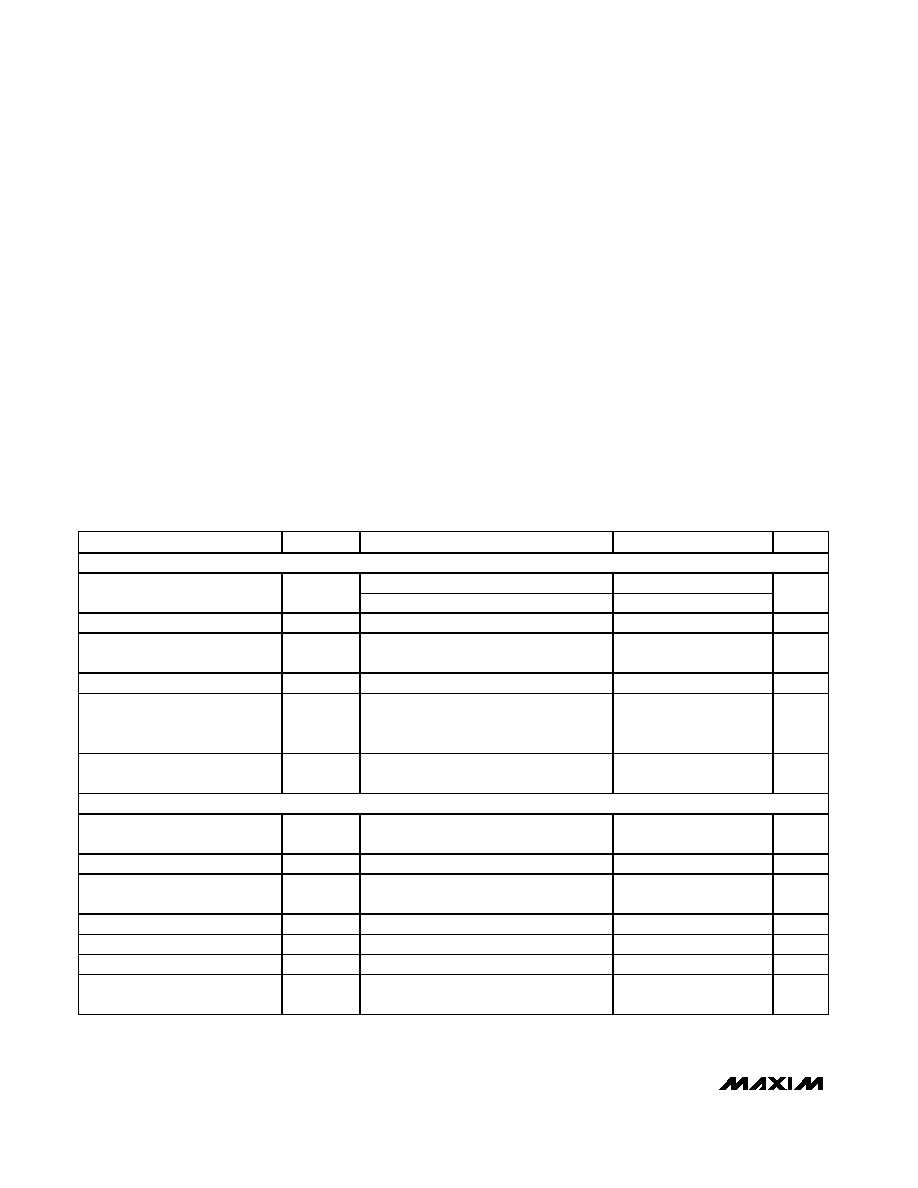
PARAMETER
SYMBOL
CONDITIONS
MIN
TYP
MAX
UNITS
INPUT SUPPLIES (Note 1)
LDO5 in regulation
6
26
V
IN
Input Voltage Range
V
IN
IN = LDO5, V
OUT5
< 4.43V
4.5
5.5
V
V
IN
Operating Supply Current
I
IN
LDO5 switched over to CSL5
15
35
µA
V
IN
Standby Supply Current
I
IN(STBY)
V
IN
= 6V to 26V, both SMPS off,
includes I
SHDN
100
170
µA
V
IN
Shutdown Supply Current
I
IN(SHDN)
V
IN
= 6V to 26V, SHDN = GND
5
17
µA
Quiescent Power Consumption
P
Q
Both SMPS on, FB3 = FB5 = SKIP = GND,
V
CSL3
= 3.5V, V
CSL5
= 5.3V, V
INA
= 15V,
I
LDOA
= 0, P
IN
+ P
CSL3
+ P
CSL5
+ P
INA
3.5
4.5
mW
V
CC
Quiescent Supply Current
I
CC
Both SMPS on, FB3 = FB5 = GND,
V
CSL3
= 3.5V, V
CSL5
= 5.3V
1.1
2.1
mA
MAIN SMPS CONTROLLERS
3.3V Output Voltage in Fixed
Mode
V
OUT3
V
IN
= 6V to 26V, SKIP = V
CC
(Note 2)
3.280
3.33
3.380
V
5V Output Voltage in Fixed Mode
V
OUT5
V
IN
= 6V to 26V, SKIP = V
CC
(Note 2)
4.975
5.05
5.125
V
Feedback Voltage in Adjustable
Mode
V
FB_
V
IN
= 6V to 26V, FB3 or FB5,
duty factor = 20% to 80% (Note 2)
0.990
1.005
1.020
V
Output-Voltage Adjust Range
Either SMPS
1.0
5.5
V
FB3, FB5 Dual-Mode Threshold
0.1
0.2
V
Feedback Input Leakage Current
V
FB3
= V
FB5
= 1.1V
-0.1
+0.1
µA
DC Load Regulation
Either SMPS, SKIP = V
CC
,
I
LOAD
= 0 to full load
-0.1
%

MAX1533/MAX1537
High-Efficiency, 5x Output, Main Power-Supply
Controllers for Notebook Computers
_______________________________________________________________________________________
3
ELECTRICAL CHARACTERISTICS (continued)
(Circuit of Figure 1, V
IN
= 12V, both SMPS enabled, V
CC
= 5V, FSEL = REF, SKIP = GND, V
ILIM_
= V
LDO5
, V
INA
= 15V, V
LDOA
= 12V,
I
LDO5
= I
LDO3
= I
LDOA
= no load, T
A
= 0°C to +85°C, unless otherwise noted. Typical values are at T
A
= +25°C.)
PARAMETER
SYMBOL
CONDITIONS
MIN
TYP
MAX
UNITS
Line-Regulation Error
Either SMPS, duty cycle = 10% to 90%
1
%
FSEL = GND
170
200
230
FSEL = REF
270
300
330
Operating Frequency (Note 1)
f
OSC
FSEL = V
CC
425
500
575
kHz
FSEL = GND
91
93
FSEL = REF
91
93
Maximum Duty Factor (Note 1)
D
MAX
FSEL = V
CC
91
93
%
Minimum On-Time
t
ON(MIN)
(Note 3)
200
ns
40
%
SMPS3 to SMPS5 Phase Shift
SMPS5 starts after SMPS3
144
Deg
CURRENT LIMIT
ILIM_ Adjustment Range
0.5
V
REF
V
Current-Sense Input Range
CSH_, CSL_
0
5.5
V
Current-Sense Input Leakage
Current
CSH_, V
CSH
_ = 5.5V
-1
+1
µA
Current-Limit Threshold (Fixed)
V
LIMIT
_
V
CSH
_ - V
CSL
_ , ILIM_ = V
CC
70
75
80
mV
V
ILIM
_ = 2.00V
170
200
230
V
ILIM
_ = 1.00V
91
100
109
Current-Limit Threshold
(Adjustable)
V
LIMIT
_
V
CSH
_ - V
CSL
_
V
ILIM
_ = 0.50V
42
50
58
mV
Current-Limit Threshold
(Negative)
V
NEG
V
CSH_
- V
CSL_
, SKIP = V
CC
, percent of
current limit
-120
%
Current-Limit Threshold (Zero
Crossing)
V
ZX
V
PGND
- V
LX
_, SKIP = GND, ILIM_ = V
CC
3
mV
ILIM_ = V
CC
10
16
22
mV
Idle-Mode
TM Threshold
V
IDLE
V
CSH
_ - V
CSL
_
With respect to current-
limit threshold (V
LIMIT
)
20
%
ILIM_ Leakage Current
ILIM3 = ILIM5 = GND or V
CC
-0.1
+0.1
µA
Soft-Start Ramp Time
t
SS
Measured from the rising edge of ON_ to
full scale
512 /
f
OSC
s
INTERNAL FIXED LINEAR REGULATORS
LDO5 Output Voltage
V
LDO5
ON3 = ON5 = GND, 6V < V
IN
< 26V,
0 < I
LDO5
< 100mA
4.80
4.95
5.10
V
LDO5 Undervoltage-Lockout Fault
Threshold
Rising edge, hysteresis = 1%
3.75
4.0
4.25
V
LDO5 Bootstrap Switch Threshold
Rising edge of CSL5, hysteresis = 1%
4.41
4.75
V
LDO5 Bootstrap Switch
Resistance
LDO5 to CSL5, V
CSL5
= 5V,
I
LDO5
= 50mA
0.75
3
Idle Mode is a trademark of Maxim Integrated Products, Inc.

MAX1533/MAX1537
High-Efficiency, 5x Output, Main Power-Supply
Controllers for Notebook Computers
4
_______________________________________________________________________________________
ELECTRICAL CHARACTERISTICS (continued)
(Circuit of Figure 1, V
IN
= 12V, both SMPS enabled, V
CC
= 5V, FSEL = REF, SKIP = GND, V
ILIM_
= V
LDO5
, V
INA
= 15V, V
LDOA
= 12V,
I
LDO5
= I
LDO3
= I
LDOA
= no load, T
A
= 0°C to +85°C, unless otherwise noted. Typical values are at T
A
= +25°C.)
PARAMETER
SYMBOL
CONDITIONS
MIN
TYP
MAX
UNITS
LDO3 Output Voltage
V
LDO3
Standby mode, 6V < V
IN
< 26V,
0 < I
LOAD
< 100mA
3.20
3.35
3.42
V
LDO3 Bootstrap Switch Threshold
Rising edge of CSL3, hysteresis = 1%
2.83
3.10
V
LDO3 Bootstrap Switch
Resistance
LDO3 to CSL3, V
CSL3
= 3.2V,
I
LDO3
= 50mA
1
3
Short-Circuit Current
LDO3 = LDO5 = GND,
CSL3 = CSL5 = GND
150
220
mA
Short-Circuit Current (Switched
Over to CSL_)
LDO3 = LDO5 = GND, V
CSL3
> 3.1V,
V
CSL5
> 4.7V
250
mA
AUXILIARY LINEAR REGULATOR (MAX1537 ONLY)
LDOA Voltage Range
V
LDOA
5
23
V
INA Voltage Range
V
INA
6
24
V
LDOA Regulation Threshold,
Internal Feedback
ADJA = GND, 0 < I
LDOA
< 120mA,
V
INA
> 13V
11.4
12.0
12.4
V
ADJA Regulation Threshold,
External Feedback
V
ADJA
0 < I
LDOA
< 120mA, V
LDOA
> 5.0V and
V
INA
> V
LDOA
+ 1V
1.94
2.00
2.06
V
ADJA Dual-Mode Threshold
0.1
0.15
0.2
V
ADJA Leakage Current
V
ADJA
= 2.1V
-0.1
+0.1
µA
LDOA Current Limit
V
LDOA
forced to V
INA
- 1V, V
ADJA
= 1.9V,
V
INA
> 6V
150
mA
Secondary Feedback Regulation
Threshold
V
INA
- V
LDOA
0.65
0.8
0.95
V
DL Duty Factor
V
INA
- V
LDOA
< 0.7V, pulse width with
respect to switching period
33
%
INA Quiescent Current
I
INA
V
INA
= 24V, I
LDOA
= no load
50
165
µA
INA Shunt Sink Current
V
INA
= 28V
10
mA
INA Leakage Current
I
INA(SHDN)
V
INA
= 5V, LDOA disabled
30
µA
REFERENCE (REF)
Reference Voltage
V
REF
V
CC
= 4.5V to 5.5V, I
REF
= 0
1.985
2.00
2.015
V
Reference Load Regulation
I
REF
= -10µA to +100µA
1.980
2.020
V
REF Lockout Voltage
V
REF(UVLO)
Rising edge, hysteresis = 350mV
1.95
V
FAULT DETECTION
Output Overvoltage Trip
Threshold
OVP = GND, with respect to error-
comparator threshold
8
11
15
%
Output Overvoltage Fault-
Propagation Delay
t
OVP
50mV overdrive
10
µs

MAX1533/MAX1537
High-Efficiency, 5x Output, Main Power-Supply
Controllers for Notebook Computers
_______________________________________________________________________________________
5
ELECTRICAL CHARACTERISTICS (continued)
(Circuit of Figure 1, V
IN
= 12V, both SMPS enabled, V
CC
= 5V, FSEL = REF, SKIP = GND, V
ILIM_
= V
LDO5
, V
INA
= 15V, V
LDOA
= 12V,
I
LDO5
= I
LDO3
= I
LDOA
= no load, T
A
= 0°C to +85°C, unless otherwise noted. Typical values are at T
A
= +25°C.)
PARAMETER
SYMBOL
CONDITIONS
MIN
TYP
MAX
UNITS
Output Undervoltage-Protection
Trip Threshold
With respect to error-comparator threshold
65
70
75
%
Output Undervoltage Fault-
Propagation Delay
t
UVP
50mV overdrive
10
µs
Output Undervoltage-Protection
Blanking Time
t
BLANK
From rising edge of ON_
6144 /
f
OSC
s
PGOOD Lower Trip Threshold
With respect to error-comparator
threshold, hysteresis = 1%
-14
-10
-7.5
%
PGOOD Propagation Delay
t
PGOOD
_
Falling edge, 50mV overdrive
10
µs
PGOOD Output Low Voltage
I
SINK
= 4mA
0.4
V
PGOOD Leakage Current
I
PGOOD
_
High state, PGOOD forced to 5.5V
1
µA
PGDLY Pullup Current
PGDLY = GND
4
5
6
µA
PGDLY Pulldown Resistance
10
25
PGDLY Trip Threshold
REF-
0.2
REF
REF+
0.2
V
Thermal-Shutdown Threshold
T
SHDN
Hysteresis = 15
°C
+160
°C
GATE DRIVERS
DH_ Gate-Driver On-Resistance
R
DH
BST_ - LX_ forced to 5V
1.5
5
DL_, high state
1.7
5
DL_ Gate-Driver On-Resistance
R
DL
DL_, low state
0.6
3
DH_ Gate-Driver Source/Sink
Current
I
DH
DH_ forced to 2.5V,
BST_ - LX_ forced to 5V
2
A
DL_ Gate-Driver Source Current
I
DL
DL_ forced to 2.5V
1.7
A
DL_ Gate-Driver Sink Current
I
DL (SINK)
DL_ forced to 2.5V
3.3
A
DL_ rising
35
Dead Time
t
DEAD
DH_ rising
26
ns
LX_, BST_ Leakage Current
V
BST
_ = V
LX
_ = 26V
<2
20
µA
INPUTS AND OUTPUTS
High
2.4
Logic Input Voltage
SKIP, hysteresis = 600mV
Low
0.8
V
High
0.7 x
V
CC
Fault Enable Logic Input Voltage
OVP, UVP, ONA
Low
0.4
V
Logic Input Current
OVP, UVP, SKIP, ONA
-1
+1
µA
Rising trip level
1.10
1.6
2.20
SHDN Input Trip Level
Falling trip level
0.96
1
1.04
V
Clear fault level/SMPS off level
0.8
Delay start level (REF)
1.9
2.1
ON_ Input Voltage
SMPS on level
2.4
V