Äîêóìåíòàöèÿ è îïèñàíèÿ www.docs.chipfind.ru
North America: Tel. (800) 366-2266, Fax (800) 618-8883
Asia/Pacific: Tel.+81-44-844-8296, Fax +81-44-844-8298
Europe: Tel. +44 (1344) 869 595, Fax+44 (1344) 300 020
Specifications subject to change without notice.
Visit www.macom.com for additional data sheets and product information.
V 4.0
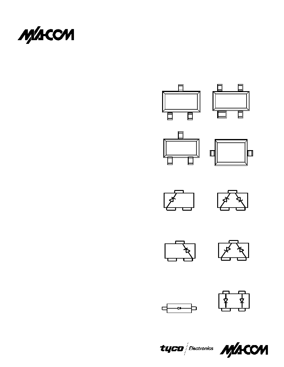
Package Outlines
Features
·
Low I
R
(<100nA @ 1V, <500nA @ 3V)
·
Designed for High Volume, Low Cost Detector and Mixer
Applications
·
Low Noise Figure: 5.7 dB (SSB) at X-Band
·
High Detector Sensitivity: -55 dBm TSS
·
Low Capacitance: 0.30 pF
·
Low 1/F Noise
·
Single, Series Pair, and Unconnected Pair Configurations
·
Available in four package styles
·
Tape and Reel
Description
The MA4E2054 series are low barrier n-type silicon Schottky
diodes assembled in low cost surface mount plastic packages.
They are designed for use as high performance mixer and
detector diodes at frequencies from VHF through low Ku band.
The MA4E2054-1141T (SOD-323), and the MA4E2054A and
the MA4E2054C (available in both the SOT-23 and SOT-323
packages) are single element Schottky diodes characterized for
use as single ended mixers and detectors. The MA4E2054B and
MA4E2054D (available in both the SOT-23 and SOT-323
packages) incorporate two Schottky chips in series pair
configurations. The MA4E2054E-1068T consists of two
Schottky chips in the SOT-143 package in an unconnected pair
configuration. These diodes are useful for balanced mixer and
detector voltage doubler circuits. Applications for the
MA4E2054 series include VSAT and DBS mixers. The small
diode package size and low cost make them attractive for use in
RF tag applications for identification and toll collection.
The part number consists of the base chip (MA4E2054),
followed by the wiring configuration (A, B, C, D, E, omit for
SOD-323), the package style (287, 1068, 1141, 1146) and a "T"
for tape and reel.
The MA4E2054-1141T is available only in the SOD-323
package style. The MA4E2054A , B, C, D are available in both
the SOT-23 and SOT-323 package styles. The MA4E2054E is
available only in the SOT-143 package style.
SOT-23 (287)
SOT-143 (1068)
SOT-323 (1146)
SOD-323 (1141)
Configurations
TOP VIEW
3
1
2
3
1
2
3
1
2
3
1
2
1
2
4
1
2
3
SINGLE
MA4E2054A-287T
MA4E2054A-1146T
SINGLE
MA4E2054C-287T
MA4E2054C-1146T
SINGLE
MA4E2054-1141T
UNCONNECTED PAIR
MA4E2054E-1068T
SERIES PAIR
MA4E2054B-287T
MA4E2054B-1146T
SERIES PAIR
MA4E2054D-287T
MA4E2054D-1146T
MA4E2054 Series
Surface Mount Low Barrier
X-Band Schottky Diode
1
North America: Tel. (800) 366-2266, Fax (800) 618-8883
Asia/Pacific: Tel.+81-44-844-8296, Fax +81-44-844-8298
Europe: Tel. +44 (1344) 869 595, Fax+44 (1344) 300 020
Specifications subject to change without notice.
Visit www.macom.com for additional data sheets and product information.
V 4.0
Maximum Ratings
Parameter
Unit
Values
Operating Temperature
ºC
-65 to +125
Storage Temperature
ºC
-65 to +125
Incident RF Power (CW)
mW
75
1
Reverse Voltage @ 25ºC
V
3
Forward Current
mA
20
Soldering Temperature
ºC
+260 for 5 sec.
1. At 25°C junction temperature. Derate linearly to zero watts at 125°C case temperature.
Electrical Specifications @ +25°C
Parameter
Condition
Symbol
Specification
Breakdown Voltage
I
R
= 10 mA
V
B
3.0 V min.
Reverse Leakage Current
V
R
= 1 V
I
R
100 nA max.
Reverse Leakage Current
V
R
= 3 V
I
R
500 nA max.
Total Capacitance
V
R
= 0 V
C
T
0.30 pF max.
Dynamic Resistance
2
I
F
= 10 mA
R
D
17 Ohms max.
Forward Voltage
I
F
= 1 mA
V
F
250 mV min.
Forward Voltage Difference
1
I
F
= 1 mA
V
F
20 mV max.
1. Applies to MA4E2054B, MA4E2054D and MA4E2054E configurations.
2. R
D
= R
S
+ R
J
where R
J
=
26
I
F
(in mA)
Typical RF Performance @ +25°C
Parameter
Conditions
Typical Value
Mixer Noise Figure
1
f = 9.375 GHz
5.7 dB (SSB)
IF Impedance
I
F
= 30 MHz
200 ohms
Tangential Signal
Sensitivity
2
I
F
= 20 mA
BW = 2 MHz
-55 dBm
Detector Output
Voltage at -30 dBm
2
R
L
= 100K Ohms
I
F
= 20
µ
A
20 mV
Detector Output
R
L
= 1M Ohm
20 mV
1. Fixture tuned to 9.375 GHz.
2. Fixture tuned to 2.5 GHz. See figures on page 3 for untuned fixture performance.
IS = 3 x 10-
8
A
M = 0.50
RS = 11
EG = 0.69 eV
N = 1.05
BV = 5.0 V
TT = 0 S
IBV = 1 x 10 -
5
A
Cj(0) = 0.10 x 10 -
12
pF
Cpar = 0.11 x 10 -
12
pF
VJ = 0.40 V
Spice Model Parameters
2
Surface Mount Low Barrier X-Band Schottky Diodes
MA4E2054 Series
North America: Tel. (800) 366-2266, Fax (800) 618-8883
Asia/Pacific: Tel.+81-44-844-8296, Fax +81-44-844-8298
Europe: Tel. +44 (1344) 869 595, Fax+44 (1344) 300 020
Specifications subject to change without notice.
Visit www.macom.com for additional data sheets and product information.
V 4.0
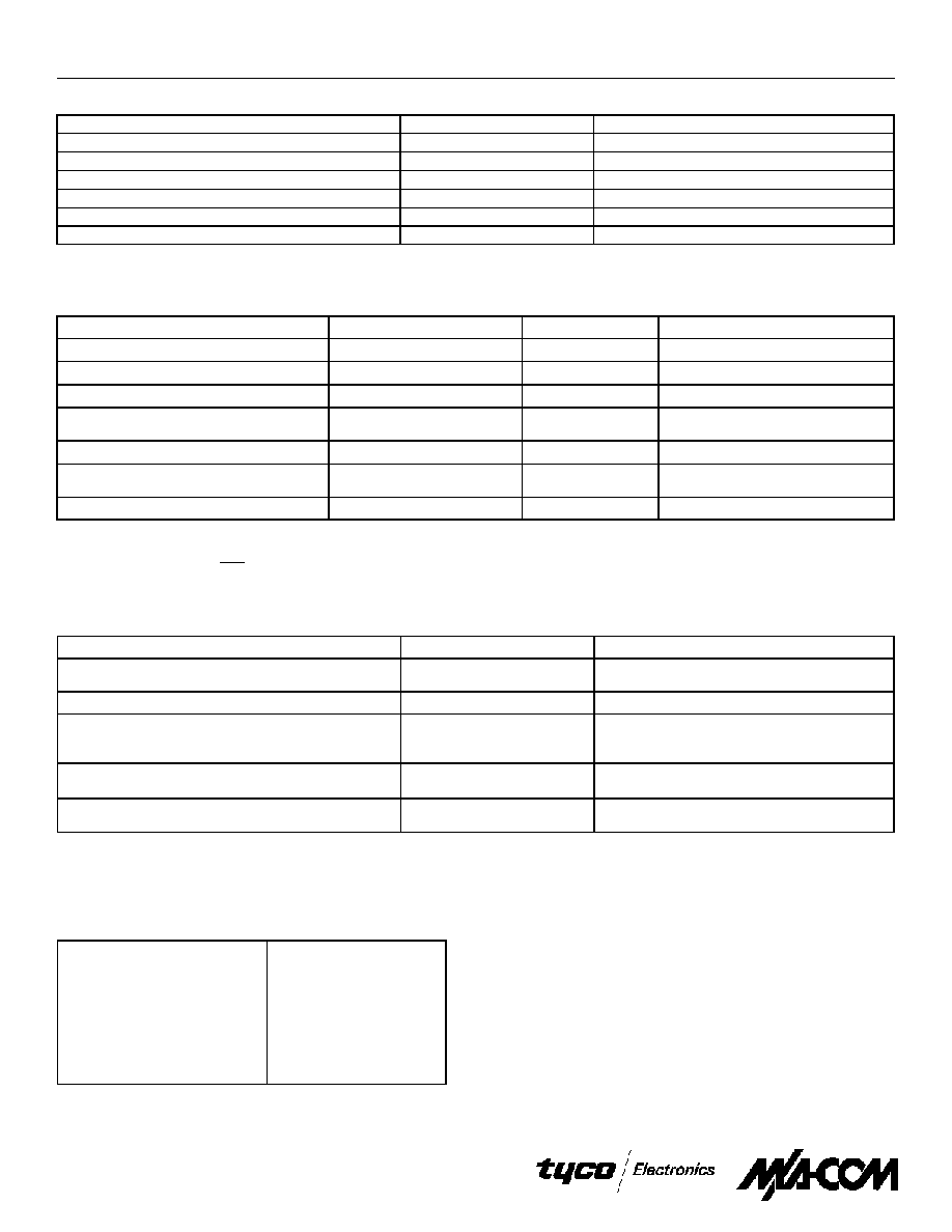
Circuit Models
SOT-23
SOT-143
.65 nH
.65 nH
.7 nH
.05 pf
.01 pf
.13 pf
.13 pf
.01 pf
.05 pf
.013 pf
.015 pf
1
2
3
C
1
C
1
C
1
C
1
C
1
Cp
1
C
1
C
1
Cp
2
Cp
3
Cp
4
1
2
4
3
7
L
BW
6
8
5
L
BW
Lg
M
M
L
1
L
1
L
1
SOT-323
SOD-323
LBW = 0.08nH, Lg = 0.36nh, L1 = 0.31nH, M = 0.12nH, C1 = 0.01pF,
Cp1 = 0.05pF, CP2 = 0.10pF, Cp3 = 0.05pF, Cp4 = 0.03pF
.6 nH
.6 nH
.6 nH
.05 pf
.06 pf
.04 pf
.04 pf
.06 pf
.05 pf
.06 pf
.04 pf
1
2
3
.47 nH
.05 pf
.02 pf
.2 pf
.47 nH
.02 pf
.2 pf
1
2
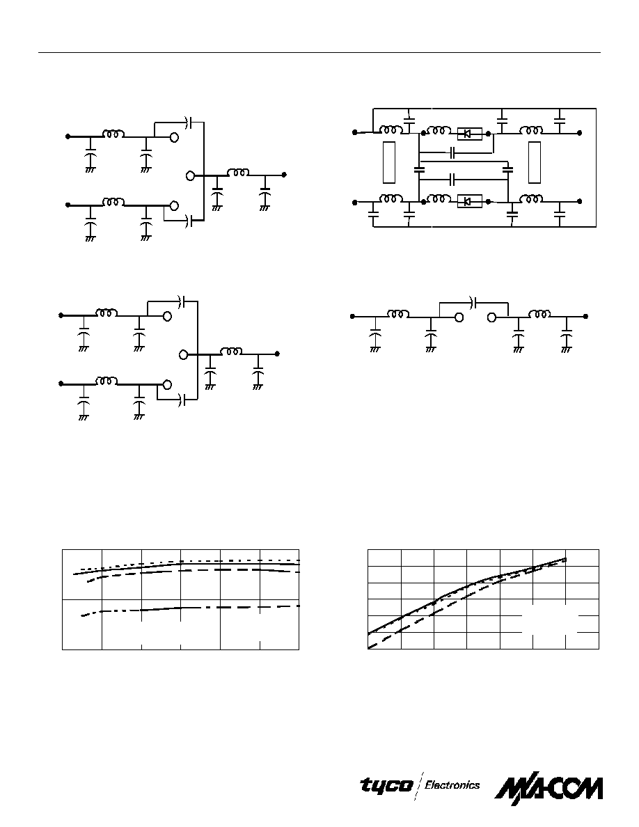
Typical Performance Curves @ 25°C
(MA4E2054-287T)
0.1
1
10
0
2
4
6
8
10
12
FR EQ U EN C Y (GH z)
V
OU
T
(m
V
)
- - - - - - 1M ohm
________
100k ohm s
__ __ __
10k ohm s
__ . . __ . .
5k ohm s
0.01
0.1
1
10
100
1000
10000
-50
-40
-30
-20
-10
0
10
20
IN PU T PO W E R (dB m )
V
OU
T
(mV)
- - - - - - 10k ohm s
________
1M ohm
__ __ __
5k ohm s
Detector Output Voltage vs Frequency and
Load Resistance at -30 dBm. Diode Forward
Biased at 20
µ
µ
µ
µ
A. Untuned Fixture (50
)
Detector Output Voltage vs Input Power and
Load Resistance. Diode Forward Biased at
20
µ
µ
µ
µ
A. Untuned Fixture at 9.375 GHz
3
Surface Mount Low Barrier X-Band Schottky Diodes
MA4E2054 Series
North America: Tel. (800) 366-2266, Fax (800) 618-8883
Asia/Pacific: Tel.+81-44-844-8296, Fax +81-44-844-8298
Europe: Tel. +44 (1344) 869 595, Fax+44 (1344) 300 020
Specifications subject to change without notice.
Visit www.macom.com for additional data sheets and product information.
V 4.0
3
4
5
6
7
8
9
0 .0 1
0 .1
1
1 0
L O P O W E R (m W )
NO
IS
E
FIG
URE
(
d
B
)
0 .0 1
0 .1
1
1 0
0
5 0
1 0 0
1 5 0
2 0 0
2 5 0
3 0 0
3 5 0
4 0 0
4 5 0
5 0 0
V
F
(m V )
I
F
(mA
)
+ 1 2 5
o
C
2 5
o
C
-5 0
o
C
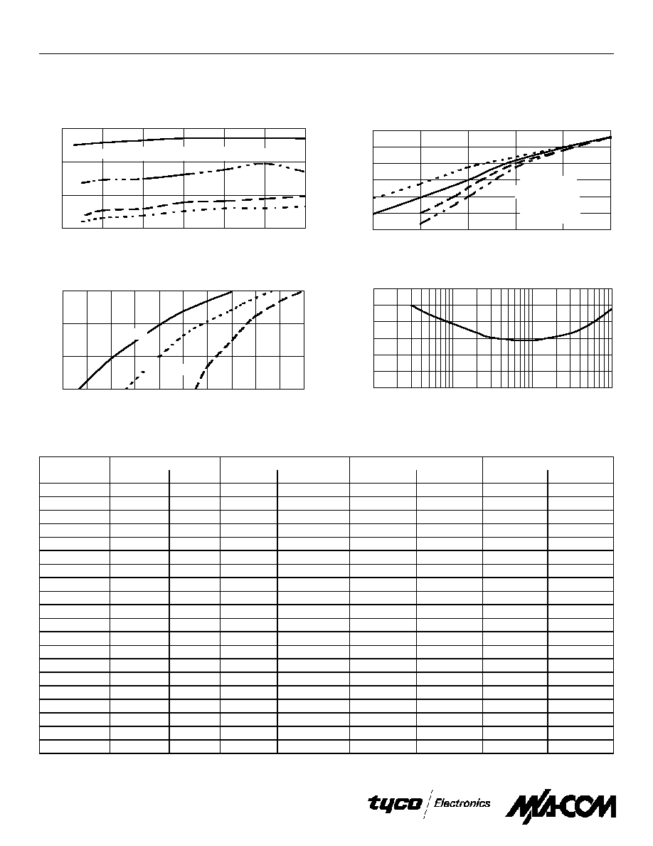
Typical Performance Curves @ 25°C (Cont'd)
(MA4E2054-287T)
Forward Current vs Forward Voltage
and Temperature
Tuned Fixture
Typical Scattering Parameters (S
11
)
MA4E2054A (packaged in SOT-23), Using a 50 Ohm Intercontinental Test Fixture (no DC bias)
Freq.
-30 dBm
-3 dBm
0 dBm
GHz
MAG
PHASE
MAG
PHASE
MAG
PHASE
MAG
PHASE
0.50
0.993
-7.6
0.812
-7.0
0.597
-4.6
0.387
-0.9
1.00
0.994
-15.1
0.843
-14.7
0.632
-13.9
0.411
-11.3
1.50
0.993
-21.4
0.807
-21.7
0.596
-22.3
0.386
-22.4
2.00
0.997
-27.1
0.791
-26.0
0.580
-23.1
0.383
-16.4
2.50
0.994
-33.2
0.795
-31.5
0.579
-27.6
0.378
-18.5
3.00
0.994
-41.3
0.755
-42.7
0.548
-45.2
0.342
-48.6
3.50
0.992
-48.6
0.727
-52.2
0.524
-55.8
0.318
-60.8
4.00
0.997
-56.5
0.713
-58.9
0.502
-59.5
0.296
-56.3
4.50
0.987
-66.4
0.696
-67.1
0.464
-67.7
0.235
-62.6
5.00
0.971
-74.7
0.634
-79.8
0.386
-86.2
0.167
-94.9
5.50
0.965
-83.1
0.614
-88.6
0.354
-91.4
0.131
-98.7
6.00
0.980
-96.0
0.547
-103.5
0.292
-107.0
0.072
-117.2
6.50
0.974
-110.3
0.514
-120.1
0.248
-129.5
0.041
163.9
7.00
0.941
-123.7
0.450
-137.4
0.235
-150.8
0.070
145.2
7.50
0.957
-138.9
0.430
-158.1
0.247
178.0
0.152
120.6
8.00
0.969
-155.6
0.404
-178.8
0.260
150.1
0.218
102.5
8.50
0.933
-171.5
0.405
162.2
0.294
129.9
0.278
92.0
9.00
0.932
170.9
0.391
143.1
0.310
110.8
0.344
84.4
9.50
0.943
152.8
0.410
128.2
0.318
97.9
0.343
68.7
10.00
0.931
132.2
0.504
108.9
0.394
83.3
0.399
56.9
3 dBm
0 .0 1
0 .1
1
1 0
1 0 0
1 0 0 0
1 0 0 0 0
-4 0
-3 0
-2 0
-1 0
0
1 0
IN P U T P O W E R (dB m )
V
OU
T
(m
V
)
- - - - - - 1 M o h m
______ __
1 0 0 k o h m s
__ _ _ _ _
1 0 k o h m s
__ . . __ . .
5 k o h m s
0 .0 1
0 .1
1
1 0
0
2
4
6
8
1 0
1 2
F R E Q U E N C Y (G H z)
V
OU
T
(m
V
)
- - - - - - 1 M o h m
__ ______
1 0 0 k o hm s
__ __ __
1 0 k o h m s
__ . . __ . .
5 k o h m s
Detector Output Voltage vs Frequency and
Load Resistance at -30 dBm. Diode at Zero
Bias. Untuned Fixture (50
)
Detector Output Voltage vs Input Power and
Load Resistance. Diode at Zero Bias. Untuned
Fixture at 9.375 GHz (50
)
4
Surface Mount Low Barrier X-Band Schottky Diodes
MA4E2054 Series
North America: Tel. (800) 366-2266, Fax (800) 618-8883
Asia/Pacific: Tel.+81-44-844-8296, Fax +81-44-844-8298
Europe: Tel. +44 (1344) 869 595, Fax+44 (1344) 300 020
Specifications subject to change without notice.
Visit www.macom.com for additional data sheets and product information.
V 4.0
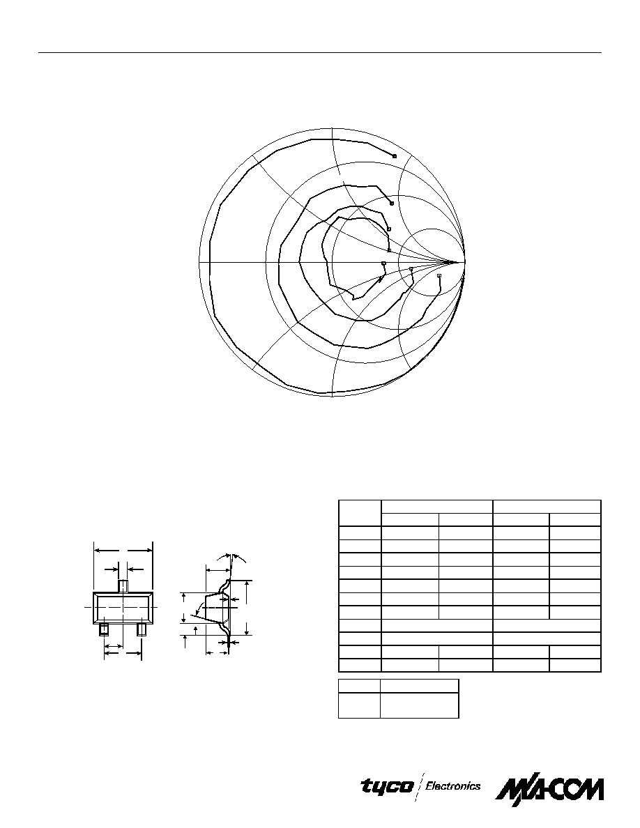
Impedance Plot
MA4E2054A (packaged in SOT-23)
Using a 50 Ohm Intercontinental Test Fixture (no DC bias)
-30 dBm
-3 dBm
0 dBm
+3 dBm
Fstart=0.5 GHz
Fstop=12.5 GHz
Case Styles
SOT-23
SOT-23 (Case 287)
F
D
H
J
A
G
L
C
E
B
K
N
M
INCHES
MILLIMETERS
DIM.
MIN.
MAX.
MIN.
MAX.
A
0.048
1.22
B
0.008
0.20
C
0.040
1.00
D
0.013
0.020
0.35
0.50
E
0.003
0.006
0.08
0.15
F
0.110
0.119
2.80
3.00
G
0.047
0.056
1.20
1.40
H
0.037 typical
0.95 typical
J
0.075 typical
K
0.103
2.60
L
0.024
0.60
1.90 typical
DIM.
GRADIENT
M
10° max.
1
Note:
N
2° . . .30°
1. Applicable on all sides
5
Surface Mount Low Barrier X-Band Schottky Diodes
MA4E2054 Series