/home/web/doc/html/holtek/189449
HT82M23A/HT82M23B/HT82M23C
3/5-Key USB+PS/2 Optical Mouse Controller
Selection Table
Part No.
Interface
Mode
USB Product ID
Package
HT82M23A
USB and PS/2
Windows 2000
048EH
20DIP/SOP
HT82M23B
USB and PS/2
3D
0499H
18DIP/SOP
HT82M23C
USB only
3D
0499H
18DIP/SOP
Rev. 1.00
1
January 25, 2006
Features
·
Operating voltage: 4.4V~5.25V
·
Compatible with Microsoft Windows 2000 and
5-button Wheel Mouse
·
Microsoft 3D Intelli mouse and IBM PS/2 mouse
compatible
·
Supports 3/5 buttons and Z-axis input
·
Z-axis can support two kinds of scroller input
(optomechanical and mechanical)
·
3 key or 5 key mode can be selected by package
·
Complete Universal Serial Bus specs V1.1
compatibility
·
Serial Bus Interface Engine (SIE)
·
USB transceiver
·
Single chip solution especially for USB mouse
function
·
HALT function and wake-up feature reduce power
consumption
·
Plug and Play functions
·
Minimal external components
·
6MHz crystal oscillator for system clock
·
Interface compliant with ADNS-2051, ADNS-2610
and ADNS-2620
·
Pass WHQL, USB-IF and EMC testing
·
HT82M23A is pin compatible with HT82M22A
·
HT82M23B/HT82M23C is pin compatible with
HT82M21A
·
HT82M23A: 20-pin DIP/SOP package
HT82M23B/HT82M23C: 18-pin DIP/SOP package
General Description
HT82M23A/HT82M23B/HT82M23C is a Plug and Play
Windows 2000 and 5-button 3D USB+PS/2 Mouse con-
troller. The HT82M23A/HT82M23B/HT82M23C can
support the USB Standard Request as well as HID Class
Request version 1.1. It is compatible with Microsoft Intelli
3D or Windows 2000 5 key PS/2 mouse. The Z-axis can
support two kinds of scroller input, namely; mechanical
and optomechanical. It requires minimal external com-
ponents to implement 3D or Windows 2000 5 key USB
plus PS/2 mouse. All its features combined and make
up this versatile Holtek 8-bit MCU with an on-chip USB
interface logic. The USB is specified by the
Universal
Serial Bus Specification V1.1.
The USB vendor ID for HT82M23A/HT82M23B/
HT82M23C is defined as 04D9H, the USB product ID is
different by different package
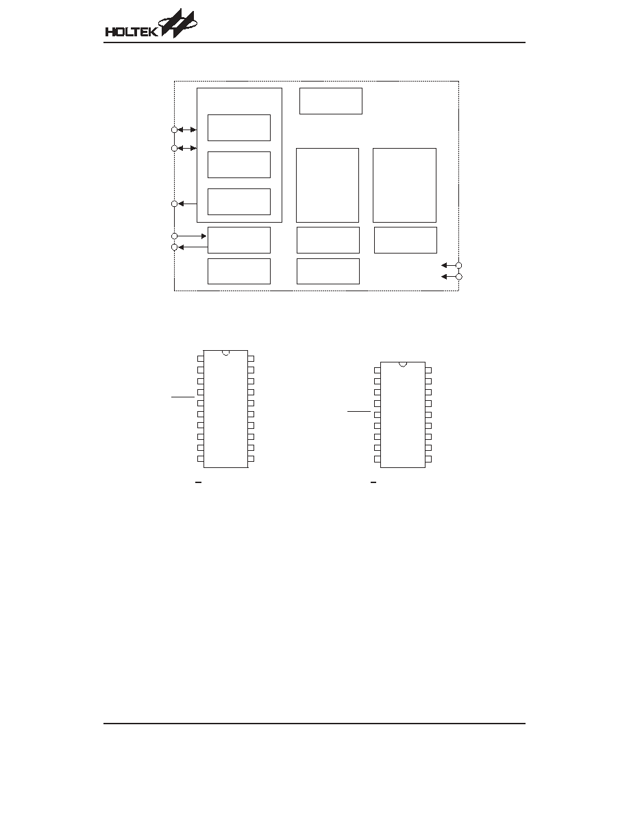
Block Diagram
Pin Assignment
HT82M23A/HT82M23B/HT82M23C
Rev. 1.00
2
January 25, 2006
V S S
V 3 3 O
U S B D + / C L K
U S B D - / D A T A
R E S E T
S E L 1
S D I O
S C L K
S E L 0
R B 0
O S C 1
O S C 2
V D D
L E D
M
R
L
Z 2
Z 1
R B 1
H T 8 2 M 2 3 A
2 0 D I P - A / S O P - A
2 0
1 9
1 8
1 7
1 6
1 5
1 4
1 3
1 2
1 1
1
2
3
4
5
6
7
8
9
1 0
1 8
1 7
1 6
1 5
1 4
1 3
1 2
1 1
1 0
1
2
3
4
5
6
7
8
9
H T 8 2 M 2 3 B / H T 8 2 M 2 3 C
1 8 D I P - A / S O P - A
V S S
V 3 3 O
U S B D + / C L K
U S B D - / D A T A
R E S E T
S E L 1
S D I O
S C L K
S E L 0
O S C 1
O S C 2
V D D
L E D
M
R
L
Z 2
Z 1
U S B
T r a n s c e i v e r
U S B
R e c e i v e r
U S B
T r a n s m i t t e r
V o l t a g e
R e g u l a t o r
C l o c k
G e n e r a t o r
R C
R E S E T
R e g i s t e r
S e t
M a i n
S t a t e m a c h i n e
S u s p e n s i o n
C o n t r o l
U S B S e r i a l
I n t e r f a c e E n g i n e
( S I E )
a n d
C o n t r o l
L o g i c
H o l t e k
8 - b i t
M i c r o c o n t r o l l e r
F I F O s ´ 2
U S B D +
U S B D -
V 3 3 O
O S C 1
O S C 2
V D D
V S S
Pin Description
Pin Name
I/O
Description
VSS
¾
Negative power supply, ground
V33O
O
3.3V voltage output
USBD+/CLK
I/O
USB data plus or PS2 Clock, F/W auto-detect USBD+ for USB, CLK for PS2
USBD
-/DATA
I/O
USB data minus or PS2 Data, F/W auto-detect USB
- for USB, DATA for PS2
RESET
I
Chip reset input, low active
SEL1
SEL0
I
Configuration selections
SEL1=0: Z-axis is divided by 2 (default)
SEL1=1: Z-axis is divided by 4
For ADNS 2051:
SEL0=0: 800DPI (default)
SEL0=1: 400DPI
For ADNS 2610/2620:
SEL0=0, 400DPI (default)
SEL0=1, 800DPI-by firmware
SDIO
I/O
Serial data for Agilent sensor IC SDIO
SCLK
I
Serial data for Agilent sensor IC SCLK
RB0, RB1
L, R, M
I
Click button detection. Input ports with 30k
W pull-high resistor.
Input ports with pull-high resistor. These pads can function as Left, Right, Middle, B4 and B5
button input lines.
Z1, Z2
I
Z-axis input supports two kinds of scroller input; optomechanical and mechanical.
LED
I/O
Drives LED output
VDD
¾
5V positive power supply
OSC2
O
6MHz OSC output
OSC1
I
6MHz OSC input
Absolute Maximum Ratings
Supply Voltage ..............................V
SS
-0.3V to V
SS
+6V
Storage Temperature ............................
-50°C to 125°C
MCU Input Voltage.....................V
SS
-0.3V to V
DD
+0.3V
Operating Temperature...........................
-25°C to 70°C
USB Input Voltage ....................V
SS
-0.3V to V
33O
+0.3V
Note: These are stress ratings only. Stresses exceeding the range specified under
²Absolute Maximum Ratings² may
cause substantial damage to the device. Functional operation of this device at other conditions beyond those
listed in the specification is not implied and prolonged exposure to extreme conditions may affect device reliabil-
ity.
HT82M23A/HT82M23B/HT82M23C
Rev. 1.00
3
January 25, 2006
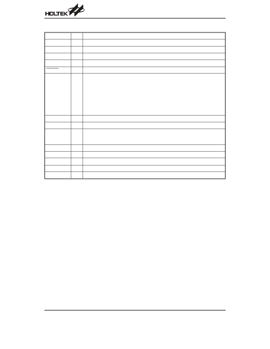
D.C. Characteristics
Ta=25
°C
Symbol
Parameter
Test Conditions
Min.
Typ.
Max.
Unit
V
DD
Conditions
V
DD
Operating Voltage
¾
¾
4.4
¾
5.25
V
I
DD
Operating Current
(Crystal OSC)
5V
No load,
f
SYS
=6MHz
USB mode
¾
10
¾
mA
PS/2 mode
¾
3
¾
mA
I
SUS
USB Suspend Mode
5V
No load, system HALT
¾
¾
250
mA
V
IL1
Input Low Voltage
(Z1, Z2, L, M, R)
5V
¾
0
¾
1.0
V
V
IH1
Input High Voltage
(Z1, Z2, L, M, R)
5V
¾
3.5
¾
5
V
V
IL2
Input Low Voltage (RESET)
5V
¾
0
¾
1.5
V
V
IH2
Input High Voltage (RESET)
5V
¾
3.5
¾
5
V
V
POR
Built-in Power on Reset V
DD
Detection Voltage
5V
¾
¾
3.7
¾
V
I
OL
Sink Current (LED)
5V
V
OL
=0.8V
¾
50
¾
mA
A.C. Characteristics
Ta=25
°C
Symbol
Parameter
Test Conditions
Min.
Typ.
Max.
Unit
V
DD
Conditions
f
SYS
System Clock (Crystal OSC)
5V
¾
0
6000
¾
kHz
Note: t
SYS
=1/f
SYS
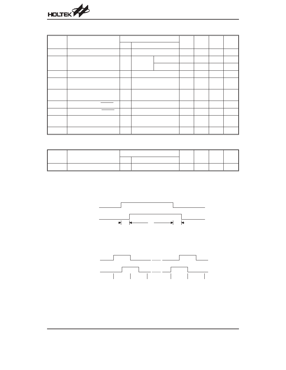
Timing Diagram
Z-axis Photo-Coupler Crossed Width
Z-axis Counting
HT82M23A/HT82M23B/HT82M23C
Rev. 1.00
4
January 25, 2006
Z 1
Z 2
t
r
t
f
t
P
N o t e : F o r Z - a x i s t
r
, t
P
, t
f
> 1 m s
Z 1
Z 2
+ 1
+ 1
- 1
- 1
HT82M23A/HT82M23B/HT82M23C
Rev. 1.00
5
January 25, 2006
Functional Description
PS/2 Mouse
·
PS/2 status byte
¨
Byte 1
Bit 7: Reserved
Bit 6: 0=Stream Mode, 1=Remote Mode
Bit 5: 0=Disabled, 1=Enabled
Bit 4: 0=Scaling 1:1, 1=Scaling 2:1
Bit 3: 1=Wrap Mode, 0=Stream or Remote
(different from IBM specs.)
Bit 2: 1=Left Button Pressed
Bit 1: 1=Middle Button Pressed
Bit 0: 1=Right Button Pressed
¨
Byte 2
Bit 0~7 current resolution setting
(Bit 0=LSB)
¨
Byte 3
Bit 0~7 current sampling rate (Bit 0=LSB)
·
Standard PS/2 data format (HT82M23A/HT82M23B)
Bit No.
7
6
5
4
3
2
1
0
1st word
YV
XV
YS
XS
1
M
R
L
2nd word
X7
X6
X5
X4
X3
X2
X1
X0
3rd word
Y7
Y6
Y5
Y4
Y3
Y2
Y1
Y0
·
Data format for 3D PS/2 (HT82M23A/HT82M23B)
Bit No.
7
6
5
4
3
2
1
0
1st word
YV
XV
YS
XS
1
M
R
L
2nd word
X7
X6
X5
X4
X3
X2
X1
X0
3rd word
Y7
Y6
Y5
Y4
Y3
Y2
Y1
Y0
4th word
Z7
Z6
Z5
Z4
Z3
Z2
Z1
Z0
Note:
The X/Y data report is 9-bit 2
¢s complement
The Z data report is 8-bit 2
¢s complement
·
Data format for 5-button Wheel Mouse (HT82M23A)
Bit No.
7
6
5
4
3
2
1
0
1st word
0
0
YS
XS
1
M
R
L
2nd word
X7
X6
X5
X4
X3
X2
X1
X0
3rd word
Y7
Y6
Y5
Y4
Y3
Y2
Y1
Y0
4th word
0
0
RB1 RB0 Z3
Z2
Z1
Z0
Note:
X- movement towards the right is positive, mov-
ing towards the left is negative
Y- upward movement is positive, moving down
is negative
Z- rolling towards the user is positive, else negative
Button status: 1=pressed, 0=released
·
For HT82M23B/HT82M23C, mouse mode changes
between Standard and 3D PS/2 mode.
Sending the commands in the following sequence will
set the mouse to 3D PS/2 mode.
Command
Response From Mouse
F3h
FAh
C8h
FAh
F3h
FAh
64h
FAh
F3h
FAh
50h
FAh
F2h
FAh, 03h
·
For HT82M23A, mouse mode changes between
Standard and Windows 2000 PS/2 mode.
Sending the commands in the following sequence will
set the mouse to Windows 2000 PS/2 mode.
Command
Response From Mouse
F3h
FAh
C8h
FAh
F3h
FAh
C8h
FAh
F3h
FAh
50h
FAh
F2h
FAh, 04h
¨
Any time the PC sends a reset
²FFh² command to
the mouse, it will reset the mouse to Standard PS/2
mode.
After power-on reset is initiated, the mouse is set to
Standard PS/2 mode.
·
USB mouse data format for 3D mod
(HT82M23A/HT82M23B/HT82M23C)
Bit No.
7
6
5
4
3
2
1
0
1st word
0
0
0
0
0
M
R
L
2nd word
X7
X6
X5
X4
X3
X2
X1
X0
3rd word
Y7
Y6
Y5
Y4
Y3
Y2
Y1
Y0
4th word
Z7
Z6
Z5
Z4
Z3
Z2
Z1
Z0
·
Data format for Windows 2000 mode (HT82M23A)
Bit No.
7
6
5
4
3
2
1
0
1st word
0
0
0
RB1 RB1
M
R
L
2nd word
X7
X6
X5
X4
X3
X2
X1
X0
3rd word
Y7
Y6
Y5
Y4
Y3
Y2
Y1
Y0
4th word
Z7
Z6
Z5
Z4
Z3
Z2
Z1
Z0
Note:
X- movement towards the right is positive, mov-
ing towards the left is negative
Y- upward movement is negative, moving down
is positive
Z- rolling towards the user is negative, else positive
Button status: 1=pressed, 0=released