Untitled Document

Technische Information / Technical Information
Netz-Thyristor-Modul
Phase Control Thyristor Module
TT W3C 145 N 12...18 (ISOPACK)
N
W3
Elektrische Eigenschaften / Electrical properties
Höchstzulässige Werte / Maximum rated values
Periodische Vorwärts- und Rückwärts-Spitzensperrspannung
T
vj
= - 40°C...T
vj max
V
DRM
, V
RRM
1200, 1400
V
repetitive peak forward off-state and reverse voltages
1600, 1800
V
Vorwärts-Stoßspitzensperrspannung
T
vj
= - 40°C...T
vj max
V
DSM
1200, 1400
V
non-repetitive peak forward off-state voltage
1600, 1800
V
Rückwärts-Stoßspitzensperrspannung
T
vj
= + 25°C...T
vj max
V
RSM
1300, 1500
V
non-repetitive peak reverse voltage
1700, 1900
V
Durchlaßstrom-Grenzeffektivwert (pro Element)
I
TRMSM
120
A
RMS on-state current (per chip)
Effektivstrom (pro Phase)
T
C
= 85°C
I
RMS
145
A
RMS current (per arm)
T
C
= 75°C
170
A
T
A
= 45°C, KM 11
40
A
T
A
= 45°C, KM 33
59
A
T
A
= 35°C, KM 14 (V
L
= 45l/s)
108
A
T
A
= 35°C, KM 33 (V
L
= 90l/s)
131
A
Stoßstrom-Grenzwert
T
vj
= 25°C, t
p
= 10ms
I
TSM
1250
A
surge current
T
vj
= T
vj max
, t
p
= 10ms
1050
A
Grenzlastintegral
T
vj
= 25°C, t
p
= 10ms
I²t
7800
A²s
I²t-value
T
vj
= T
vj max
, t
p
= 10ms
5500
A²s
Kritische Stromsteilheit
DIN IEC 747-6
(di/dt)
cr
120
A/µs
critical rate of rise of on-state current
f = 50Hz, i
GM
= 0,6A, di
G
/dt = 0,6A/µs
Kritische Spannungssteilheit
T
vj
= T
vj max
, v
D
= 0,67 V
DRM
(dv/dt)
cr
critical rate of rise of off-state voltage
8. Kennbuchstabe / 8th letter F
1000
V/µs
Charakteristische Werte / Characteristic values
Durchlaßspannung
T
vj
= T
vj max
, i
T
= 200A
v
T
max.
1,87
V
on-state voltage
Schleusenspannung
T
vj
= T
vj max
V
(T0)
0,95
V
threshold voltage
Ersatzwiderstand
T
vj
=T
vj max
r
T
3,2
m
slope resistance
Zündstrom
T
vj
= 25°C, v
D
= 6V
I
GT
max.
150
mA
gate trigger current
Zündspannung
T
vj
= 25°C, v
D
= 6V
V
GT
max.
2,5
V
gate trigger voltage
Nicht zündender Steuerstrom
T
vj
= T
vj max
, v
D
= 6V
I
GD
max.
5,0
mA
gate non-trigger current
T
vj
= T
vj max
, v
D
= 0,5 V
DRM
max.
2,5
mA
Nicht zündende Steuerspannung
T
vj
= T
vj max
, v
D
= 0,5 V
DRM
V
GD
max.
0,2
V
gate non-trigger voltage
Haltestrom
T
vj
= 25°C, v
D
= 6V, R
A
= 5
I
H
max.
200
mA
holding current
Einraststrom
T
vj
= 25°C, v
D
= 6V, R
GK
20
I
L
max.
600
mA
latching current
i
GM
= 0,6A, di
G
/dt = 0,6A/µs, t
g
= 10µs
Vorwärts- und Rückwärts-Sperrstrom
T
vj
= T
vj max
i
D
, i
R
max.
10
mA
forward off-state and reverse currents
v
D
= V
DRM
, v
R
= V
RRM
Zündverzug
DIN IEC 747-6
t
gd
max.
1,2
µs
gate controlled delay time
T
vj
= 25°C, i
GM
= 0,6A, di
G
/dt = 0,6A/µs
MOD-E1; R. Jörke
29. Apr 99
A /99
Seite/page 1(9)

Technische Information / Technical Information
Netz-Thyristor-Modul
Phase Control Thyristor Module
TT W3C 145 N 12...18 (ISOPACK)
N
W3
Elektrische Eigenschaften / Electrical properties
Charakteristische Werte / Characteristic values
Freiwerdezeit
T
vj
= T
vj max
, i
TM
= 50A
t
q
circuit commutated turn-off time
v
RM
= 100V, V
DM
= 0,67 V
DRM
d
VD
/dt = 20V/µs, -di
T
/dt = 10A/µs
7. Kennbuchstabe / 7th letter O
typ.
190
µs
Isolations-Prüfspannung
RMS, f = 50Hz, t = 1min
V
ISOL
3,0
kV
insulation test voltage
RMS, f = 50Hz, t = 1sec
3,6
kV
Thermische Eigenschaften / Thermal properties
Innerer Wärmewiderstand
pro Modul / per module,
= 180°sin
R
thJC
max. 0,070
°C/W
thermal resistance, junction to case
pro Element / per chip,
= 180°sin
max. 0,420
°C/W
pro Modul / per module, DC
max. 0,065
°C/W
pro Element / per chip, DC
max. 0,390
°C/W
Übergangs-Wärmewiderstand
pro Modul / per module
R
thCK
max. 0,033
°C/W
thermal resistance, case to heatsink
pro Element / per chip
max. 0,200
°C/W
Höchstzulässige Sperrschichttemperatur
T
vj max
125
°C
max. junction temperature
Betriebstemperatur
T
c op
- 40...+125
°C
operating temperature
Lagertemperatur
T
stg
- 40...+130
°C
storage temperature
Mechanische Eigenschaften / Mechanical properties
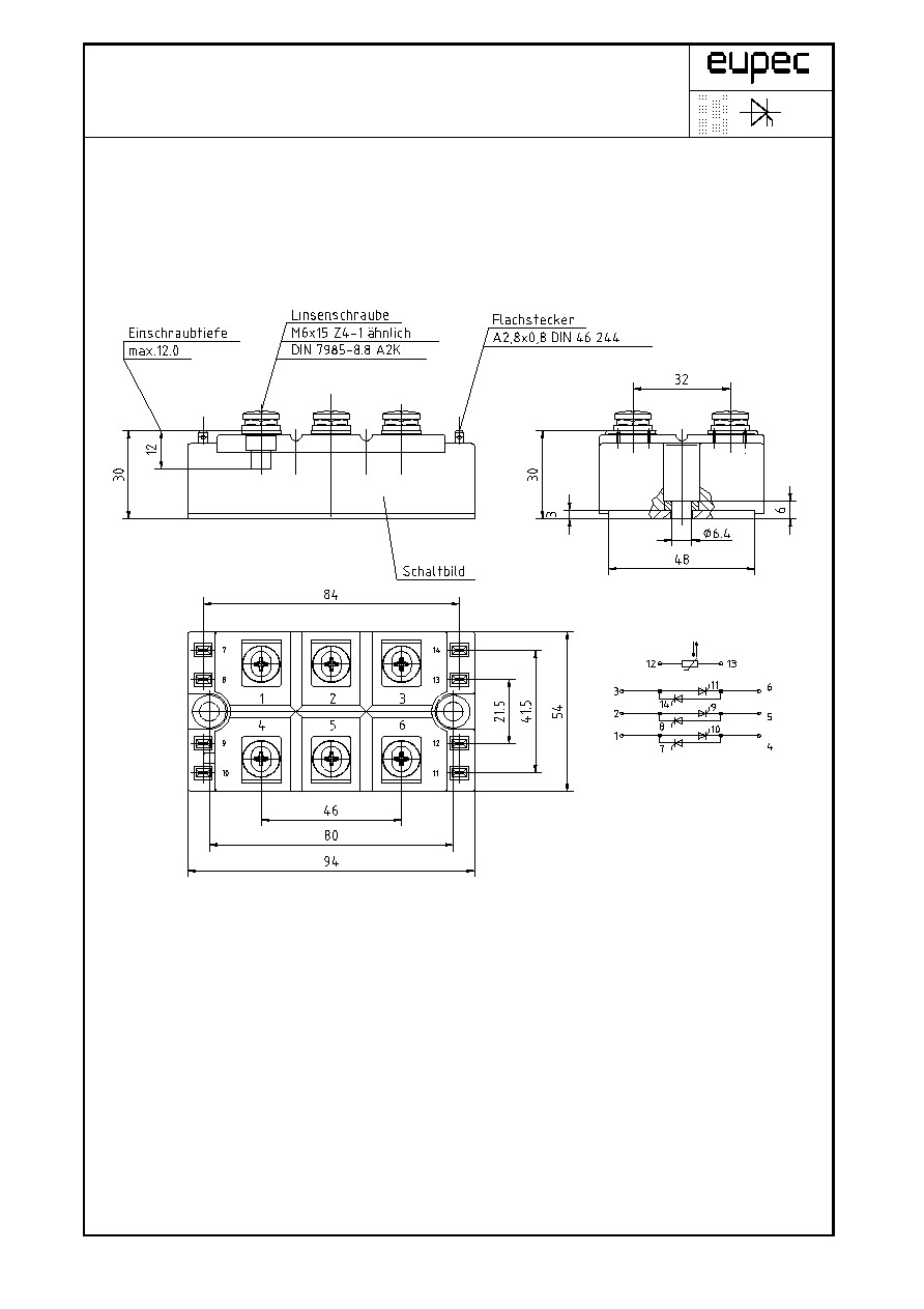
Gehäuse, siehe Anlage
Seite 3
case, see appendix
page 3
Si-Elemente mit Lötkontakt, glaspassiviert
Si-pellets with soldered contact, glass-passivated
Innere Isolation
Al
2
O
3
internal insulation
Anzugsdrehmoment für mechanische Befestigung
Toleranz / tolerance ±15%
M1
6
Nm
mounting torque
Anzugsdrehmoment für elektrische Anschlüsse
Toleranz / tolerance +5% / -10%
M2
6
Nm
terminal connection torque
Gewicht
G
typ.
300
g
weight
Kriechstrecke
12,5
mm
creepage distance
Schwingfestigkeit
f = 50Hz
50
m/s²
vibration resistance
Temperatursensor / Temperature sensor
Nennwiderstand
T
C
= 25°C
R
25
5
k
rated resistance
R
100
= 493
± 5%
Verlustleistung
T
C
= 25°C
P
25
max.
20
mW
power dissipation
Kühlkörper / heatsinks : KM 11; KM 14; KM 17; KM 33
Mit dieser technischen Information werden Halbleiterbauelemente spezifiziert, jedoch keine Eigenschaften zugesichert. Sie gilt in Verbindung
mit den zugehörigen Technischen Erläuterungen. / This technical Information specifies semiconductor devices but promises no characteristics.
It is valid in combination with the belonging technical notes.
MOD-E1; R. Jörke
29. Apr 99
Seite/page 2(9)
Technische Information / Technical Information
Netz-Thyristor-Modul
Phase Control Thyristor Module
TT W3C 145 N 12...18 (ISOPACK)
N
W3
MOD-E1; R. Jörke
29. Apr 99
Seite/page 3(9)

Technische Information / Technical Information
Netz-Thyristor-Modul
Phase Control Thyristor Module
TT W3C 145 N 12...18 (ISOPACK)
N
W3
Analytische Elemente des transienten Wärmewiderstandes Z
thJC
für DC
Analytical elements of transient thermal impedance Z
thJC
for DC
Pos. n
1
2
3
4
5
6
7
0,15200
0,21100
0,02960
0,31800
0,03870
0,00109
MOD-E1; R. Jörke
29. Apr 99
Seite/page 4(9)
[
]
R
C W
thn
°
/
[ ]
n
s
Analytische Funktion
Z
R
e
thJC
thn
t
n
n
n
:
max
=
-
-
=
1
1
Technische Information / Technical Information
Netz-Thyristor-Modul
Phase Control Thyristor Module
TT W3C 145 N 12...18 (ISOPACK)
N
W3
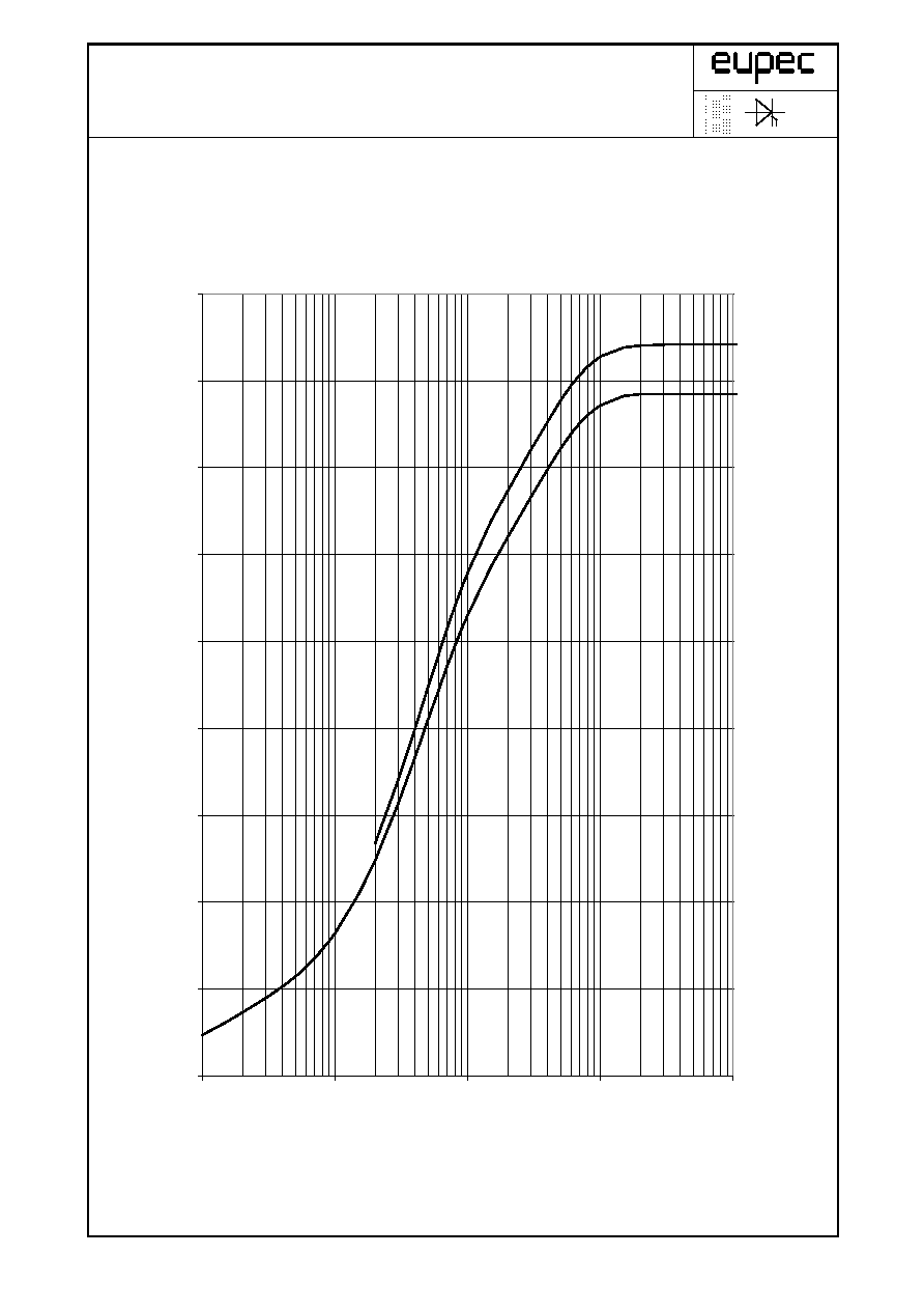
Transienter innerer Wärmewiderstand je Zweig / Transient thermal impedance per arm Z
thJC
= f(t)
Parameter: Stromflußwinkel / Current conduction angle
MOD-E1; R. Jörke
29. Apr 99
Seite/page 5(9)
180° sin
DC
0,00
0,05
0,10
0,15
0,20
0,25
0,30
0,35
0,40
0,45
0,001
0,01
0,1
1
10
t [s]
Z
thJ
C
[°
C
/
W
]
Technische Information / Technical Information
Netz-Thyristor-Modul
Phase Control Thyristor Module
TT W3C 145 N 12...18 (ISOPACK)
N
W3
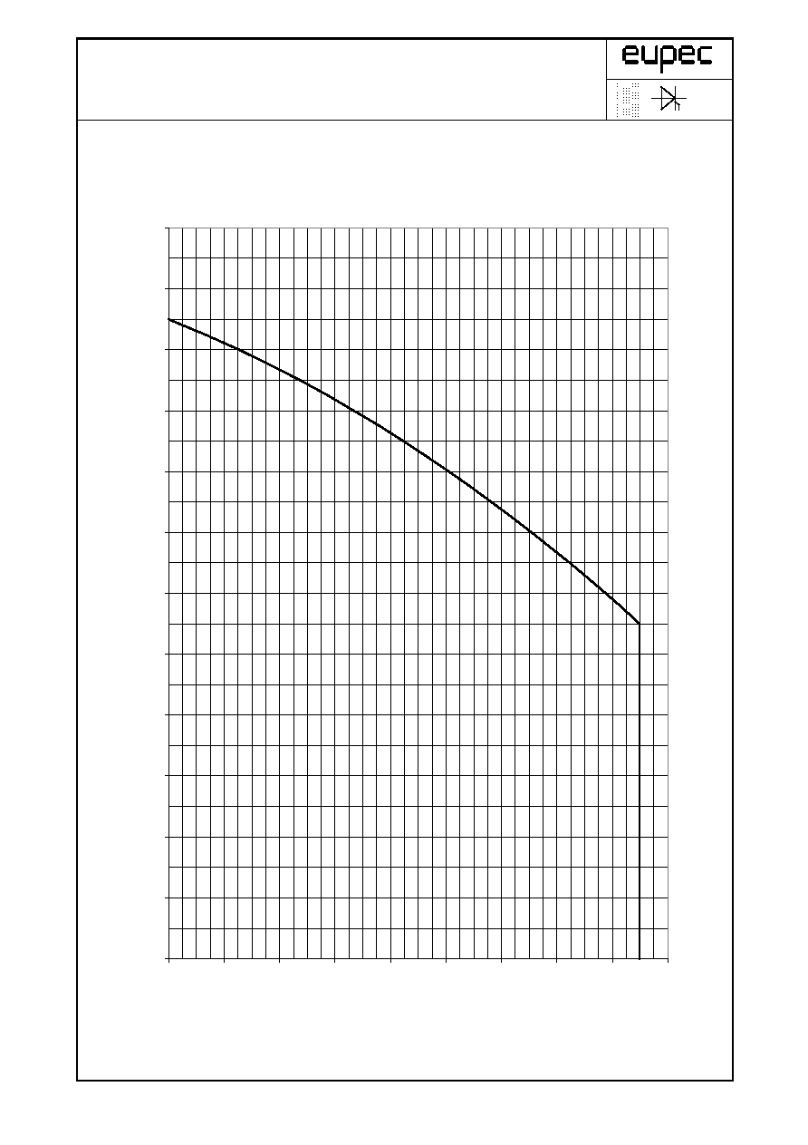
Höchstzulässige Gehäusetemperatur / Maximum allowable case temperatur T
C
= f(I
RMS
)
MOD-E1; R. Jörke
29. Apr 99
Seite/page 6(9)
20
30
40
50
60
70
80
90
100
110
120
130
140
0
20
40
60
80
100
120
140
160
180
I
RMS
[A]
T
C
[°
C
]

Technische Information / Technical Information
Netz-Thyristor-Modul
Phase Control Thyristor Module
TT W3C 145 N 12...18 (ISOPACK)
N
W3
Differenz zwischen Sperrschicht- und Sensortemperatur / Difference between the values of junction and
sensor temperature (T
vj
- T
Sensor
) = f(I
a
/ I
RMS(Tc=85°C)
)
I
a
: Anlaufstrom / Starting current
I
RMS
: Effektivstrom (pro Phase) / RMS current (per arm)
MOD-E1; R. Jörke
29. Apr 99
Seite/page 7(9)
0
10
20
30
40
50
60
70
80
90
100
0,0
0,5
1,0
1,5
2,0
I
a
/ I
RMS(Tc=85°C)
(T
vj
- T
S
ens
or
) [
°
C]
Technische Information / Technical Information
Netz-Thyristor-Modul
Phase Control Thyristor Module
TT W3C 145 N 12...18 (ISOPACK)
N
W3
Sensorwiderstand / Sensor resistance R
Sensor
= f(T
Sensor
)
MOD-E1; R. Jörke
29. Apr 99
Seite/page 8(9)
100
1000
10000
20
30
40
50
60
70
80
90
100
110
120
T
Sensor
[°C]
R
S
ens
or
[
]

Technische Information / Technical Information
Netz-Thyristor-Modul
Phase Control Thyristor Module
TT W3C 145 N 12...18 (ISOPACK)
N
W3
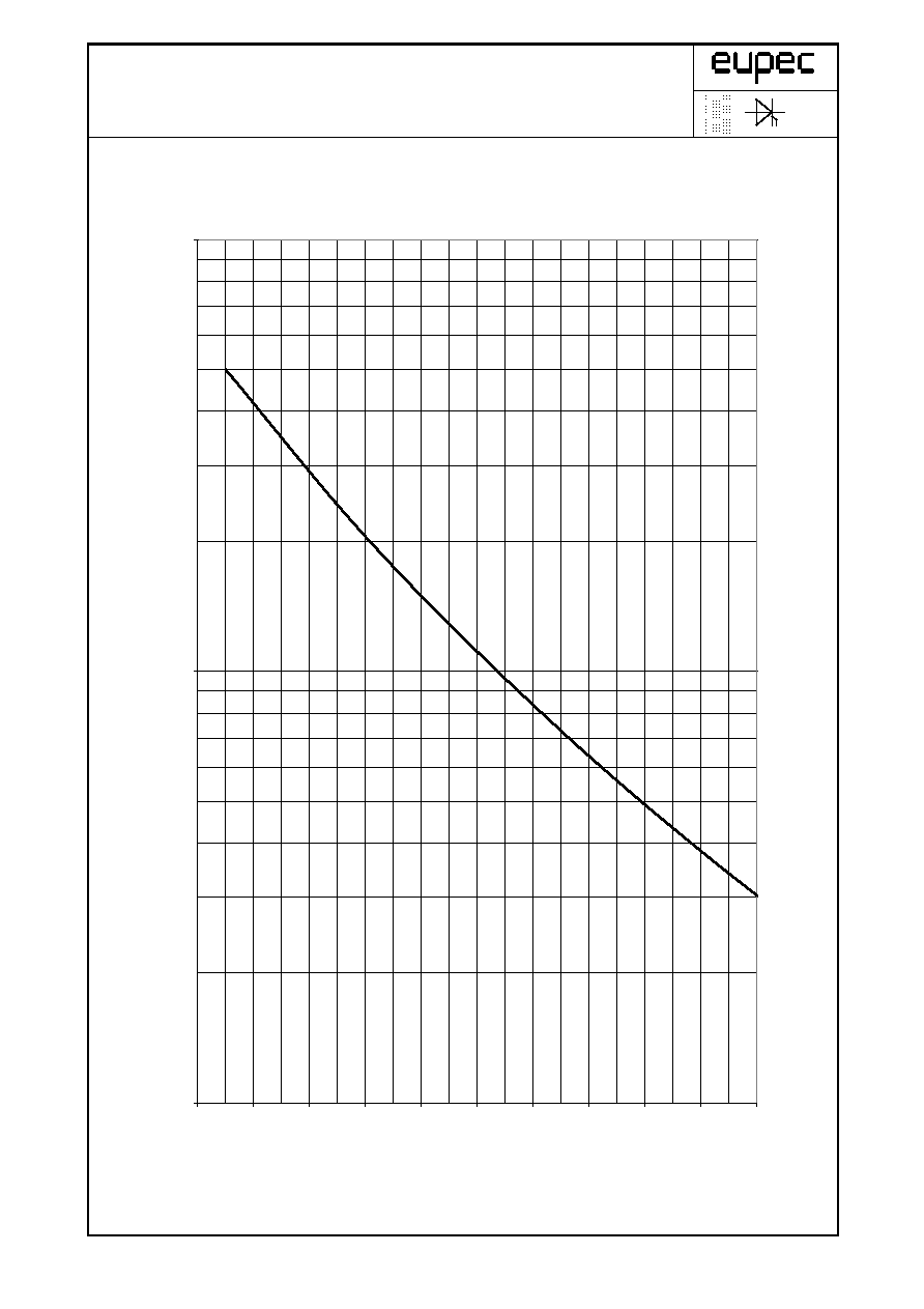
Gesamtverlustleistung pro Modul / Total power dissipation per module P
tot
= f(I
RMS
)
I
RMS
: Effektivstrom (pro Phase) / RMS current (per arm)
MOD-E1; R. Jörke
29. Apr 99
Seite/page 9(9)
0
100
200
300
400
500
600
700
800
0
20
40
60
80
100
120
140
160
180
I
RMS
[A]
P
tot
[W
]