Äîêóìåíòàöèÿ è îïèñàíèÿ www.docs.chipfind.ru
This document contains information on a new product.
Specifications and information are subject to change without notice
WJ Communications, Inc
· Phone 1-800-WJ1-4401 · FAX: 408-577-6620 · e-mail: sales@wj.com · Web site: www.wj.com
May 2002
The Communications Edge
TM
Preliminary Product Information
AH201
Medium Power, High Linearity Amplifier
z
Product Features
·
400 2200 MHz
·
+30 dBm P1dB
·
+47 dBm Output IP3
·
17 dB Gain @ 900 MHz
·
MTBF >100 Years
·
Single Positive Supply (9-12V)
·
Internally Matched
·
24dBm IS-95 Channel Power
@ -45dBc ACPR
Product Description
The AH201 is a 1W driver amplifier that offers
excellent dynamic range in a low cost, 6x6mm
surface mount package. This device can be biased as
low as +9V for lower power applications and as high
as +12V for improved P1dB and OIP3 performance.
The backside metalization allows excellent thermal
dissipation while allowing visible evidence of solder
reflow throughout the bottom of the package on a
SMT board. Superior thermal design allows the
product an MTBF of over 100 years at a mounting
temperature of +85ºC. All devices are 100% RF &
DC tested.
The product is targeted for use as driver amplifiers for
wireless infrastructure where high linearity and
medium power is required.
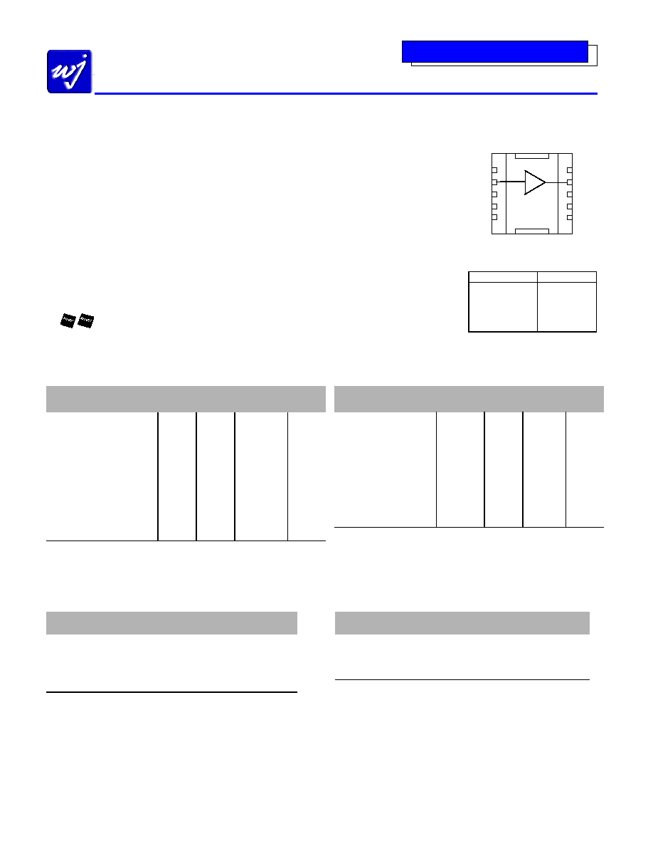
Functional Diagram
1
6
5
10
Top View
Function Pin
No.
Input 2
Output/Bias 9
Ground
1, 2, 3, 5
Ground
6, 7, 8, 10
Not Connected
4
Specifications
Parameters
Units Min
Typ.
Max
Frequency Range
MHz
400-2200
S21 - Gain
dB
15
S11 - Input Return Loss
dB
-9.5
S22 - Output Return Loss
dB
-10
Noise Figure
dB
4
Output P1dB
dBm
+30
Output IP3
dBm
+47
Operating Current Range
mA
310
330 370
Supply Voltage
V
11
Thermal Resistance
Rth
14
Test conditions unless otherwise noted.
1. T = 25ºC, Vdd = 11V, Frequency = 800 MHz, 50 Ohm system.
2. 3OIP measured with two tones at an output power of 10 dBm/tone separated by 10 MHz.
The suppression on the largest IM3 product is used to calculate the 3OIP using a 2:1 rule.
Typical Specifications
Parameters
Units
Typical
Frequency
MHz
900
1900
2200
S21 - Gain
dB
17
15
14
S11 - Input R.L.
dB
-13
-9.5
-9.3
S22 - Output R.L.
dB
-15
-9.5
-9.0
Noise
Figure
dB 3.8 4.3 4.4
Output
P1dB
dBm +30.0 +29.5 +29.3
Output IP3
dBm
+47
+47
+47
IS-95 Channel Power
@ -45dBc ACPR
dBm +24 +23.6
+23.5
Typical parameters reflect performance in an application circuit.
1. T = 25ºC, Vdd = 11V
2. 3OIP measured with two tones at an output power of 10 dBm/tone separated by 10 MHz.
The suppression on the largest IM3 product is used to calculate the 3OIP using a 2:1 rule.
Recommended Maximum Rating
Ordering Information
Parameters
Rating
Part No.
Description
Operating Case Temperature
-40 to +85
°C
AH201
Med. Power High Linearity Amp.
Storage Temperature
-40 to +125
°C
(Available in Tape & Reel)
DC Voltage
+15 V
AH201-PCB-900
400-1000 MHz Evaluation Board
RF Input Power (continuous)
+20 dBm
AH201-PCB-1900
1600-2200 MHz Evaluation Board
Junction Temperature
+155
° C
Actual Size
This document contains information on a new product.
Specifications and information are subject to change without notice
WJ Communications, Inc
· Phone 1-800-WJ1-4401 · FAX: 408-577-6620 · e-mail: sales@wj.com · Web site: www.wj.com
May 2002
The Communications Edge
TM
Preliminary Product Information
AH201
Medium Power, High Linearity Amplifier
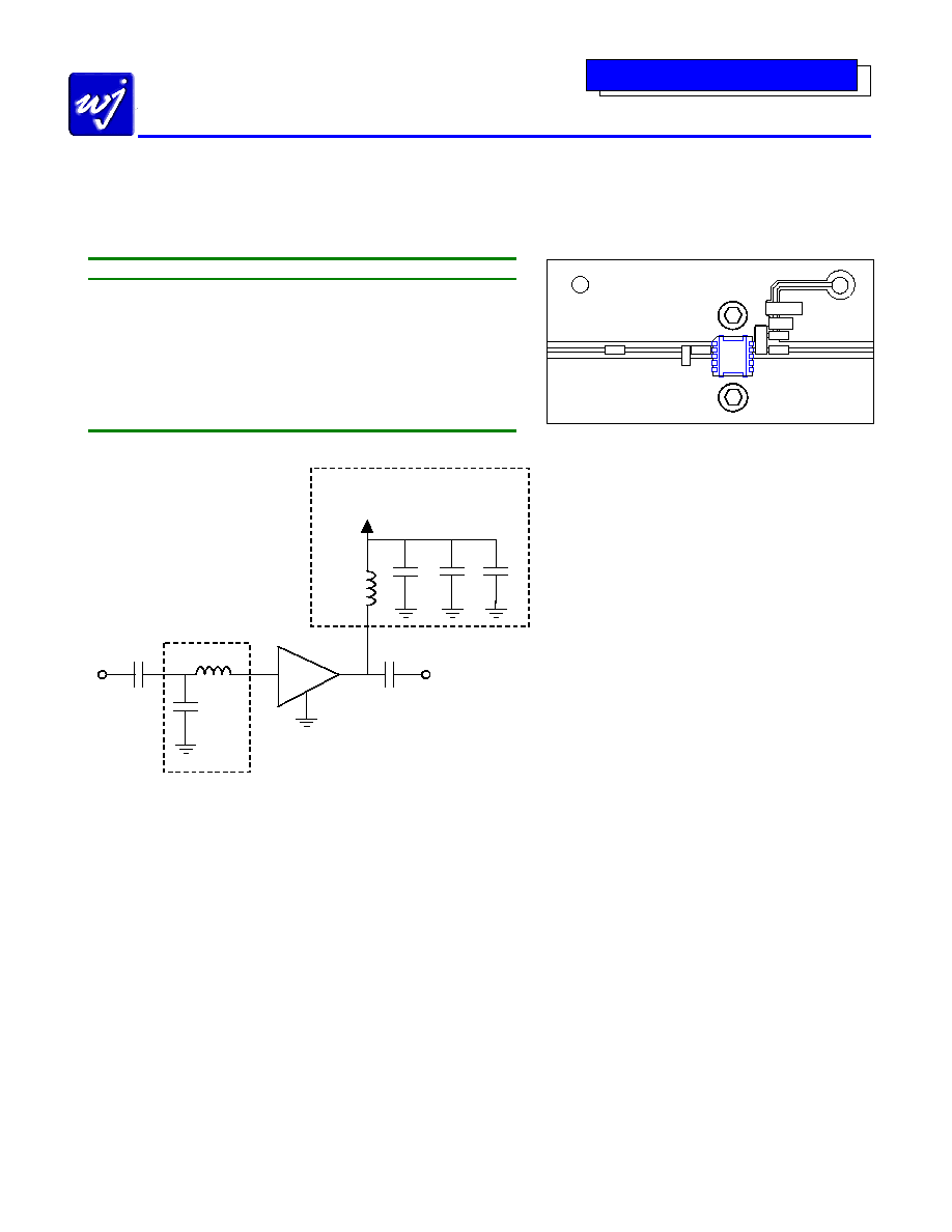
Application Circuit: 900 MHz and 1900 MHz
Typical Specifications
Frequency
MHz
900
1900
2200
S21 - Gain
dB
17
15
14
S11 - Input R.L.
dB
-13
-9.5
-9.3
S22 - Output R.L.
dB
-15
-9.5
-9.0
Noise Figure
dB
3.8
4.3
4.4
Output P1dB
dBm
+30.0
+29.5
+29.3
Output IP3
dBm
+47
+47
+47
IS-95 Channel Power
@ -45dBc ACPR
dBm +24 +23.6
+23.5
C1 C2
L1
AH201
L1
C3
C4
C5
C6
GND
Vs
RF In
RF Out
Board Material:
14 mil GETEK (
r
= 4.1)
Line Width:
28 mil
Line Spacing:
36 mil
Notes:
· Via holes are omitted for clarity.
· The microstrip line is weakly co-planer. Ground planes
around it are not necessary for operation of the AH201.
· Adequate heat sinking is required for the device.
Further mounting instructions will be shown in the
"Mounting Configuration" section of this datasheet on
the next revision for the datasheet.
· The pin configuration must be soldered accordingly
(shown on the "Functional Diagram").
· The 900 MHz application circuit board is labeled as
AH201-PCB-900.
· The 1900 MHz and 2200 MHz application circuit board
is labeled as AH201-PCB-1900.
AH201
PIN 2
PIN 9
L1
C1
56 pF
INPUT MATCH
RF OUT
L2
22 nH
V
S
= +11 V
I
D
= 330 mA C4
56 pF
DC BIAS
C3
56 pF
CIRCUIT SCHEMATIC
C2
C5
0805
1000 pF
C6
1206
.018
µF
RF IN
900 MHz
1900 MHz
2200 MHz
L1 = 3.3 nH
L1 = 0
L1 = 0
C2 = 2.2 pF
C2 = no load
C2 = no load
AH201-PCB-900 AH201-PCB-1900 AH201-PCB-1900
This document contains information on a new product.
Specifications and information are subject to change without notice
WJ Communications, Inc
· Phone 1-800-WJ1-4401 · FAX: 408-577-6620 · e-mail: sales@wj.com · Web site: www.wj.com
May 2002
The Communications Edge
TM
Preliminary Product Information
AH201
Medium Power, High Linearity Amplifier
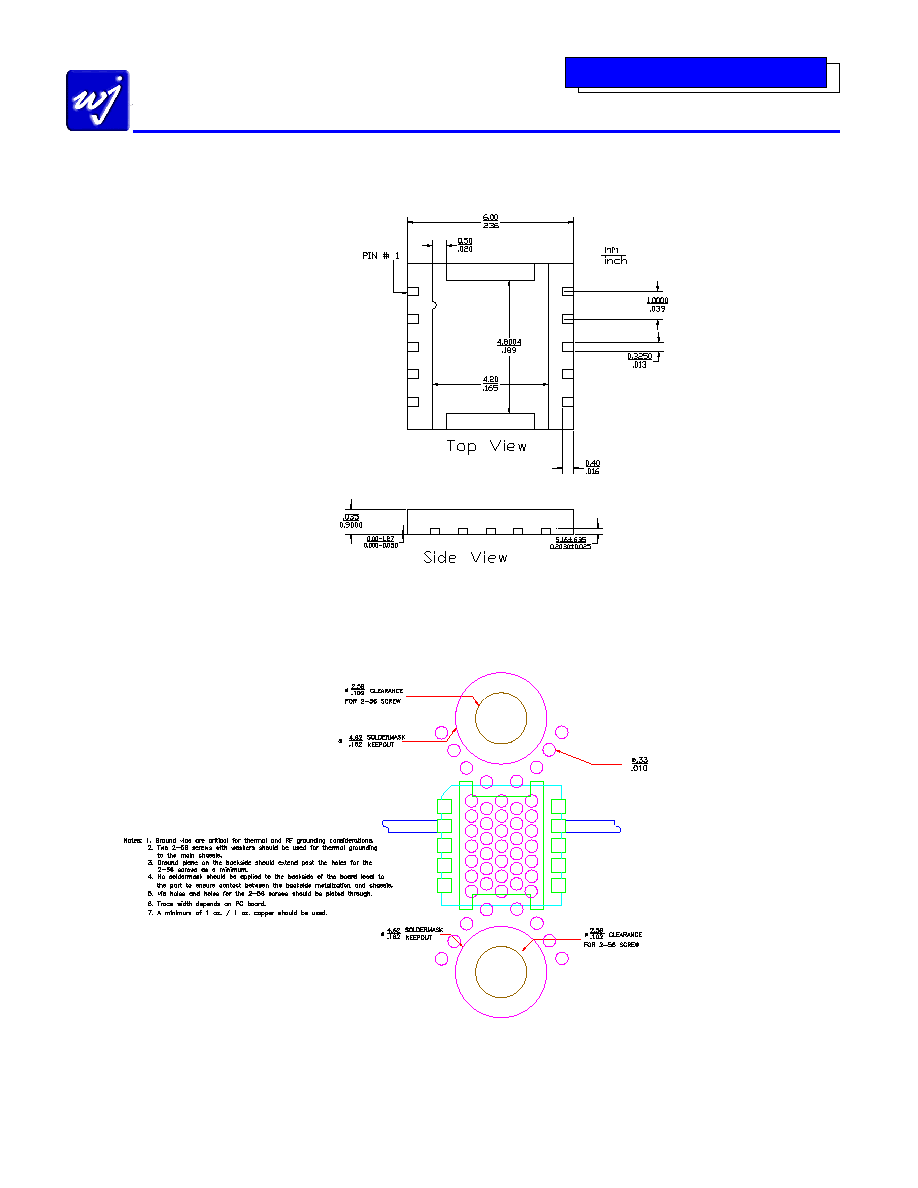
Outline Drawing
Mounting Configuration

This document contains information on a new product.
Specifications and information are subject to change without notice
WJ Communications, Inc
· Phone 1-800-WJ1-4401 · FAX: 408-577-6620 · e-mail: sales@wj.com · Web site: www.wj.com
May 2002
The Communications Edge
TM
Preliminary Product Information
AH201
Medium Power, High Linearity Amplifier
Typical Test Data
S-Parameters (V
DS
= +10V, I
DS
= 360 mA, T = 25
°
°
°
°C, unmatched device in a 50
system)
Freq (MHz)
S11 (dB)
S11 (ang)
S21 (dB)
S21 (ang)
S12 (dB)
S12 (ang)
S22 (dB)
S22 (ang)
200 -18.13 -141.77 17.77 156.16 -21.60 -12.80 -15.22 158.80
400 -14.01 -151.43 17.47 134.85 -22.01 -27.05 -15.91 138.77
600 -11.32 -161.69 17.03 113.80 -22.50 -40.65 -19.50 119.22
800 -9.60 -175.43 16.52 93.61 -23.08 -54.53 -28.09 86.76
1000 -8.38 170.85 15.98 74.11 -23.75 -66.32 -28.42 -67.31
1200 -7.72 156.06 15.50 55.43 -24.58 -80.56 -18.92 -96.94
1400 -7.51 140.70 15.09 37.11 -25.23 -94.35 -14.49 -115.52
1600 -7.69 123.37 14.78 18.41 -25.58 -107.34 -11.68 -131.45
1800 -8.42 102.05 14.63 -0.87 -26.55
-124.66
-9.76
-146.54
2000 -9.90 76.87 14.53 -21.84 -26.58 -144.30 -7.87 -160.86
2200 -12.60 27.48 14.50 -45.98 -26.08 -170.04 -7.03 -176.78
2400 -11.30 -52.35 14.07 -74.59 -25.82 158.59 -7.07 169.02
2600 -6.47 -110.35 12.82 -105.64 -25.42 125.63 -7.82 159.81
2800 -3.46
-149.16
10.54
-135.77
-25.19 97.73 -8.39 158.80
3000 -2.00 -178.37 7.60 -161.74 -25.67 70.96 -7.81 158.95
S-Parameters (V
DS
= +11V, I
DS
= 360 mA, T = 25
°
°
°
°C, unmatched device in a 50
system)
Freq (MHz)
S11 (dB)
S11 (ang)
S21 (dB)
S21 (ang)
S12 (dB)
S12 (ang)
S22 (dB)
S22 (ang)
200 -18.23 -140.99 17.78 156.01 -21.55 -12.99 -15.65 157.55
400 -13.98 -150.55 17.45 134.66 -21.89 -26.89 -16.32 136.16
600 -11.28 -161.20 17.01 113.54 -22.42 -40.61 -20.06 113.27
800 -9.55 -174.85 16.51 93.30 -22.97 -54.78 -28.14 66.80
1000 -8.37 170.96 15.97 73.75 -23.63 -68.09 -25.96 -57.60
1200 -7.72 156.06 15.48 54.97 -24.49 -80.75 -18.30 -91.67
1400 -7.52 140.70 15.06 36.62 -25.19 -92.07 -14.20 -111.26
1600 -7.63 123.63 14.76 17.90 -25.65 -110.24 -11.62 -128.20
1800 -8.33 101.89 14.61 -1.59 -26.17
-126.52
-9.75
-144.01
2000 -9.90 76.65 14.52 -22.62 -26.54 -146.07 -7.92 -158.95
2200 -12.60 27.68 14.47 -46.91 -26.12 -171.34 -7.13 -174.81
2400 -11.31 -52.94 14.03 -75.60 -25.97 158.68 -7.18 170.91
2600 -6.49 -110.68 12.76 -106.82 -25.45 124.53 -7.89 162.45
2800 -3.44
-149.63
10.46
-136.86
-25.52 96.19 -8.36 161.68
3000 -2.05 -178.91 7.50 -162.88 -25.80 71.90 -7.77 161.32
S-Parameters (V
DS
= +12V, I
DS
= 360 mA, T = 25
°
°
°
°C, unmatched device in a 50
system)
Freq (MHz)
S11 (dB)
S11 (ang)
S21 (dB)
S21 (ang)
S12 (dB)
S12 (ang)
S22 (dB)
S22 (ang)
200 -18.35 -139.11 17.75 155.83 -21.46 -12.62 -16.01 156.27
400 -13.96 -149.61 17.42 134.38 -21.90 -27.52 -16.71 134.14
600 -11.27 -160.54 16.97 113.21 -22.28 -41.26 -20.68 108.17
800 -9.51 -174.44 16.46 92.97 -22.95 -54.74 -27.61 52.71
1000 -8.29 171.17 15.92 73.44 -23.62 -66.33 -24.66 -52.59
1200 -7.65 156.23 15.44 54.51 -24.34 -80.72 -17.92 -86.86
1400 -7.46 140.57 15.02 36.13 -25.26 -95.25 -14.07 -108.70
1600 -7.60 123.49 14.70 17.27 -25.70 -109.40 -11.57 -126.27
1800 -8.36 102.04 14.55 -2.24 -26.19
-126.14
-9.74
-142.18
2000 -9.83 76.66 14.45 -23.38 -26.34 -147.66 -7.94 -157.44
2200 -12.66 26.81 14.41 -47.75 -26.11 -171.50 -7.19 -173.18
2400 -11.27 -53.63 13.95 -76.69 -25.80 158.48 -7.30 172.65
2600 -6.43 -111.31 12.64 -107.97 -25.53 126.43 -8.02 164.30
2800 -3.48
-150.13
10.33
-138.03
-25.41 96.00 -8.31 164.25
3000 -2.07 -179.12 7.37 -163.88 -25.85 70.82 -7.60 163.02