ELM624
Elm Electronics Circuits for the Hobbyist
< http://www.elmelectronics.com/ >
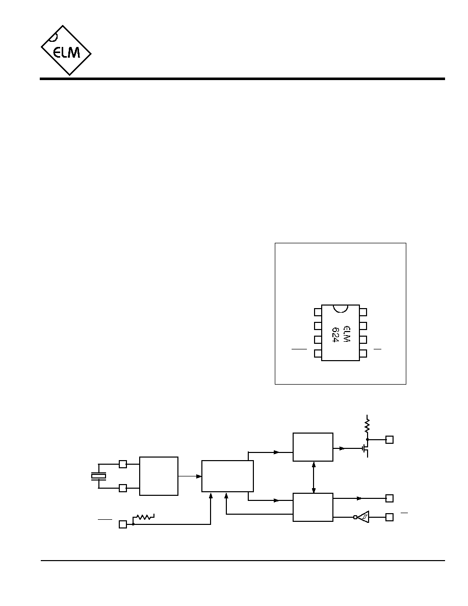
Connection Diagram
PDIP and SOIC
(top view)
V
DD
V
SS
Control L to RS232 Interpreter
The Control L or LANC interface is an industry
standard for many audio and video devices. It uses a
bit serial format that is similar to RS232, but differs
enough that devices cannot be directly connected to
one another. The ELM624 provides the necessary
logic to allow almost transparent transfer between
the two systems.
In operation, commands are sent to the ELM624
using an RS232 serial connection, translated to the
Control L format, and sent to the controlled device
on the LANC port. The resulting responses are then
converted to a series of ASCII characters and
transmitted back to the controlling serial device.
This integrated circuit was designed to provide a
cost-effective way for experimenters to work with the
Control L system, so many features typically found in
commercial devices, such as RS232 handshaking,
variable baud rates, extra buffering of signals, etc.
have not been implemented. Responses are kept to
a minimum as well (eg. a single question mark is
returned for a misunderstood command), but the
general principles are demonstrated, and for many
applications, this is all that is required.
· Low power CMOS design
· High speed RS232 communications
· Configurable with standard AT commands
· ASCII output formatted as standard hex digits
· Minimum of external components required
· Most Control L formats supported
· External reset input for system use
· Crystal controlled for signal accuracy
· Video editors
· Time-lapse recording controllers
· Remote camera controls
· Computer control of A/V equipment
LANC
Tx
Description
Applications
Block Diagram
1 of 7
Features
ELM624DSB
reset
Rx
1
2
3
8
7
6
5
4
XT1
XT2
Tx
RS232
Interface
Control
5
Control L
Interface
3.58MHz
2
3
XT1
XT2
Master
Oscillator
V
DD
reset
4
6
LANC
7
V
DD
V
SS
Rx

ELM624
Elm Electronics Circuits for the Hobbyist
< http://www.elmelectronics.com/ >
Pin Descriptions
Ordering Information
These integrated circuits are available in either the 300 mil plastic DIP format, or in the 200 mil SOIC surface
mount type of package. To order, add the appropriate suffix to the part number:
300 mil Plastic DIP............................... ELM624P
200 mil SOIC..................................... ELM624SM
2 of 7
All rights reserved. Copyright ©1999 & 2000 Elm Electronics.
Every effort is made to verify the accuracy of information provided in this document, but no representation or warranty can be
given and no liability assumed by Elm Electronics with respect to the accuracy and/or use of any products or information
described in this document. Elm Electronics will not be responsible for any patent infringements arising from the use of these
products or information, and does not authorize or warrant the use of any Elm Electronics product in life support devices and/or
systems. Elm Electronics reserves the right to make changes to the device(s) described in this document in order to improve
reliability, function, or design.
V
DD
(pin 1)
This pin is the positive supply pin, and should
always be the most positive point in the circuit.
Internal circuitry connected to this pin is used to
provide power on reset of the microprocessor, so
an external reset signal is not required. Refer to
the Electrical Characteristics section for further
information.
XT1 (pin 2) and XT2 (pin 3)
A 3.579545MHz NTSC television colourburst
crystal is connected between these two pins.
Crystal loading capacitors (typically 27pF) will
also normally be connected between each of the
pins and Vss.
reset (pin 4)
This pin can be used to reset the circuit by
applying a momentary logic low level to it. If
unused, this pin should either be connected to
V
DD
, or left open (as an internal pullup resistor is
provided).
Rx (pin5)
The computer's RS232 transmit signal is directly
connected to this pin through a single current
limiting resistor (typically about 47K
). Internal
signal inversion and Schmitt trigger waveshaping
provide the necessary signal conditioning.
Tx (pin 6)
The RS232 data output pin. Signal level is
compatible with most interface ICs, and drive is
sufficient to allow interfacing using only a single
PNP transistor if desired. See the Example
Application section for more details.
LANC (pin 7)
This is the open drain Control L (LANC) interface
pin. An internal pullup resistor is provided for a
nominal drain load.
V
SS
(pin 8)
Circuit common is connected to this pin. This is
the most negative point in the circuit.
ELM624DSB
Elm Electronics Circuits for the Hobbyist
< http://www.elmelectronics.com/ >
ELM624
Electrical Characteristics
Absolute Maximum Ratings
Storage Temperature....................... -65°C to +150°C
Ambient Temperature with
Power Applied....................................-40°C to +85°C
Voltage on V
DD
with respect to V
SS
............ 0 to +7.5V
Voltage on any other pin with
respect to V
SS
........................... -0.6V to (V
DD
+ 0.6V)
Note:
Stresses beyond those listed here will likely damage
the device. These values are given as a design
guideline only. The ability to operate to these levels
is neither inferred nor recommended.
3 of 7
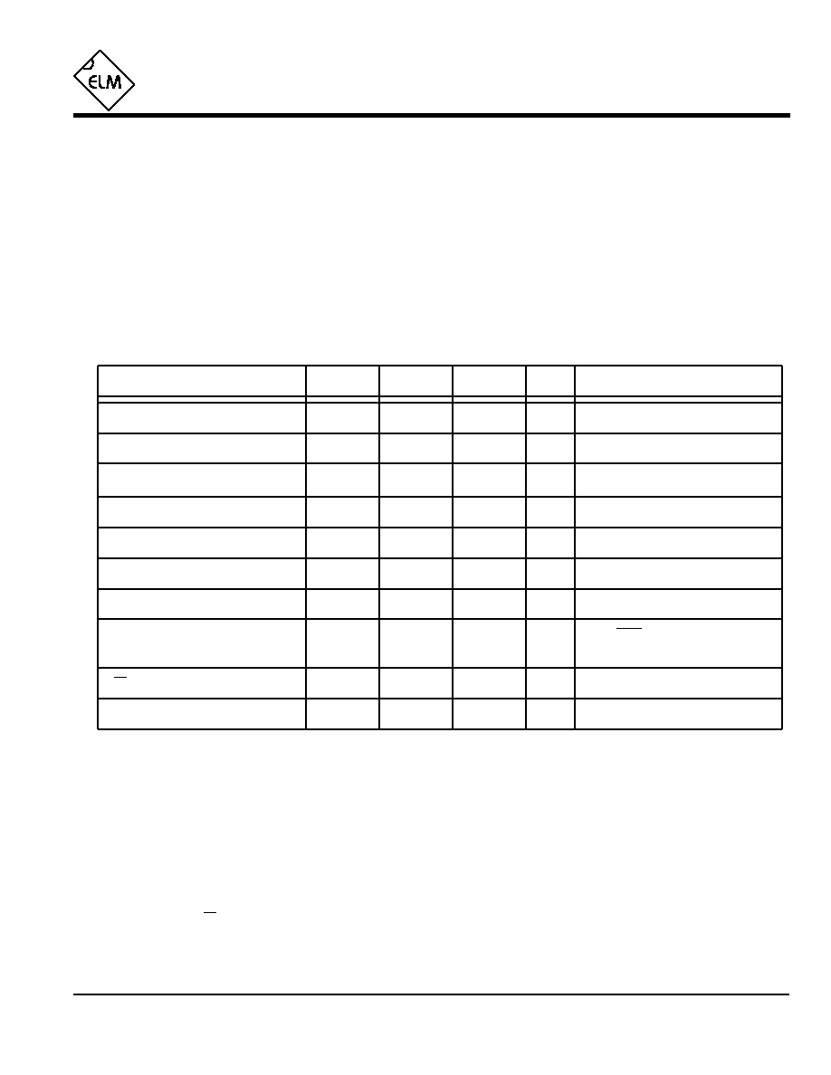
All values are for operation at 25°C and a 5V supply, unless otherwise noted. For further information, refer to note 1 below.
Characteristic
Minimum
Typical
Maximum
Conditions
Units
Supply Voltage, V
DD
4.5
5.0
5.5
V
V
DD
rate of rise
0.05
V/ms
Average Supply Current, I
DD
1.0
2.4
mA
Notes:
1. This integrated circuit is produced with a Microchip Technology Inc.'s PIC12C5XX as the core embedded
microcontroller. For further device specifications, and possibly clarification of those given, please refer to the
appropriate Microchip documentation.
2. This spec must be met in order to ensure that a correct power on reset occurs. It is quite easily achieved
using most common types of supplies, but may be violated if one uses a slowly varying supply voltage, as
may be obtained through direct connection to solar cells, or some charge pump circuits.
3. Device only. Does not include any load currents.
4. The value of the internal pullup resistance is both supply and temperature dependent.
5. This specification represents the current flowing through the protection diodes when applying large voltages
to the Rx input (pin 5) through a current limiting resistance. Currents quoted are the maximum continuous.
6. Nominal data transfer rate. Assumes that a 3.58 MHz crystal is used as a frequency reference. Data is
transferred to and from the ELM624 with 8 data bits, no parity, and 1 stop bit (8 N 1).
Input low voltage
V
SS
0.15 V
DD
V
Input high voltage
V
DD
V
0.85 V
DD
Output low voltage
0.6
V
Output high voltage
V
V
DD
- 0.7
Current (sink) = 8.7mA
Current (source) = 5.4mA
see note 2
ELM624DSB
Internal pullup resistances
(see note 4)
500
K
300
600
Pin 4 (reset)
see note 3
Rx pin input current
mA
see note 5
-0.5
Pin 7 (LANC)
K
30
20
50
RS232 Baud Rate
baud
see note 6
9600
+0.5

4 of 7
ELM624
ELM624DSB
Elm Electronics Circuits for the Hobbyist
< http://www.elmelectronics.com/ >
AT Commands
The ELM624 can accept internal configuration
commands at any time, in much the same manner that
modems do. Any command sent to the ELM624 that
begins with the characters A followed by T is
considered an internal configuration or `AT' command.
These are executed upon receipt of the terminating
carriage return character, and acceptance of a
command is acknowledged by the printing of the
characters `OK'.
The factory default settings should be sufficient for
most applications, and communications on the LANC
port can generally begin without requiring the issuance
of any AT commands, but some users may wish to
customize settings, such as turning the character echo
off, etc.
The following summarizes the `AT' commands that
are recognized by the ELM624. Note that the
character `0' is the number `zero':
Communicating with the ELM624
The ELM624 relies on a standard RS232 type
serial connection to communicate with the user. All
commands are sent to, and responses are received
from the ELM624 over this interface. The RS232 data
rate is fixed at 9600 baud, with 8 data bits, no parity
bit, 1 stop bit, and no handshaking (often referred to as
9600 8N1).
Properly connected and powered, the ELM624 will
initially display the message:
ELM624 v1.0 (c)1999
In addition to identifying the version of the IC,
receipt of this string is a convenient way for users to
be sure that their connections are correct. After
displaying this message, the integrated circuit will be
ready for a command on the RS232 port, and will wait
indefinitely until a valid one is received.
Commands can either be for internally configuring
the ELM624, or for passing on to the LANC port. The
internal commands are distinguished by always
beginning with the characters `AT', while the two
Control L bytes are simply a series of four hex digits.
See the following sections for further details.
Some other characteristics to note concerning the
commands are that extra characters are not permitted
(spaces, tabs, etc.), all commands must be terminated
with a carriage return character (hex `0D'), and the
ELM624 is not case-sensitive (so `ATZ' is equivalent to
`atz', as is `AtZ').
Understood and executed `AT' commands are
signalled by the transmission of the two characters
`OK', while any misunderstood commands (syntax
errors) are signalled by a single question mark (`?')
being sent. When Control L commands are executed,
correct completion is signalled by the ELM624
transmitting the four status bytes received from the
LANC bus (sent as eight hexadecimal digits). To
reduce RS232 traffic, all responses are terminated
with a single carriage return character, and no line
feed character. Some users may wish to have their
software insert these linefeed characters to improve
readability.
There is a possibility that incomplete data strings
could be sent to the ELM624 for one reason or
another. To avoid problems in these cases, the
ELM624 will automatically time out and abort any
incomplete command after about 20 seconds. It will
then print a single question mark, and wait for the next
command to be sent.
One last note involves the internal priorities
assigned to the two busses. In all cases, the RS232
bus takes priority over the LANC bus, and will cause
any LANC transmissions to abort if activity is detected
on the RS232 bus.
ATC0 and ATC1
These commands specify when the Control L status
bytes are to be returned on the RS232 bus. With
the C1 command, values are only sent when there
is a change from the previous four, while with C0
they are always sent. For most devices, setting C1
will have little noticeable effect, as the LANC
responses usually alternate between status and
time-code values, thus continually change. The
default is C1.
ATD0 and ATD1
These commands determine whether the first two
Control L words (0 and 1) are to be duplicated in
the next two words (2 and 3). If D0 is selected,
duplication will not occur, and words 2 and 3 will be
sent as `zeros', while setting D1 will force the words
to be duplicated. The default is D1.

5 of 7
ELM624
ELM624DSB
Elm Electronics Circuits for the Hobbyist
< http://www.elmelectronics.com/ >
Data Transfer - The LANC Protocol
Any valid four digit hex code that is received on
the RS232 port will be converted to Control L format
and transmitted out the LANC pin. The ELM624 makes
no effort to determine whether the codes are valid or
not. After sending the command, all responses
received on the port are reported back to the RS232
port using standard ASCII characters for the eight
hexadecimal digits that represent the 4 bytes received.
Note that control characters are not sent - the
hexadecimal digit `A' is transmitted as decimal value
65, not 10.
All transfers on the LANC bus occur at a rate
determined by the device being controlled. The
camcorder, or other device provides all of the timing or
synchronizing pulses for the data transfer, and the
ELM624 (in this case) must sense these sync pulses
in order to send or receive data. If the controlled
device is not providing these pulses for any reason, a
`NO SYNC' error will result - check your cables and
power supplies.
A Control L `data frame' consists of 8 sequential
bytes. Commands to the device (from the ELM624)
are sent during the first half of the frame, while the
second half (last four bytes) are for feedback from the
controlled device. Often, four bytes are not enough to
send all of the information, so data is multiplexed over
several frames. An example of this is the time codes
which contain information on days, hours, minutes and
seconds which require several bytes to represent.
The ELM624 does not send a command on the
LANC bus until it has received four valid hex digits and
a carriage return. The digits are combined in pairs to
form the first two words to be sent on the Control L bus
and, depending on the ATD option, may also be
duplicated and sent on the interface as bytes 3 and 4.
In the Control L standard, the first byte sent
usually signifies the type of device being spoken to
(eg. 1 for VTR and 2 for camera), as well as an
identifying device number. These correspond to the
first and second hex digits sent to the ELM624,
respectively. The second byte (digits 3 and 4) is the
actual command being sent. For example, the four
character command string:
1 0 3 4
would normally be interpreted as `VTR #0 Play', as the
code for play is 34. Similarly, 1030 would stop the
same VTR. Typical control codes follow:
30 Stop
36 Rewind
32 Pause
38 Fast Forward
34 Play
3A Record
8C Counter Reset
The Control L device will respond with a sequence
of 4 bytes (8 hex digits). The first byte (two digits) is
always a status byte, having typical values as follows:
02 Stopped
03 Fast Forwarding
04 Recording
06 Playing
72 Stopped - at tape beginning
83 Rewinding
The next nibble (third digit) is used to identify the
ATE0 and ATE1
These commands control whether characters
received on the RS232 port are retransmitted (or
echoed) back to the host computer. To reduce
traffic on the RS232 bus, users may wish to turn
echoing off by issuing E0. Default is E1, echo on.
ATRn where `n' is a Hex Digit
This sets the LANC command repeat value.
Although commands are only sent from the
computer to the ELM624 once, they are sent on the
Control L bus multiple times. While the Control L
standard requires that commands must be repeated
at least four successive times to be valid, the ATR
command allows this parameter to be modified for
experimentation or non-standard applications. The
default value is five (R5), and commands are
always sent at least once (R0 is treated as R1).
ATI
This causes the IC to identify itself. It simply sends
the power-on string (for a version 1.0 IC, it is
`ELM624 v1.0 (c)1999') and returns to the
command mode.
ATZ
This combination causes the chip to perform a
complete reset as if power were cycled off and then
on again. All settings are returned to their default
values.