®
ADC574A
FPO
Microprocessor-Compatible
ANALOG-TO-DIGITAL CONVERTER
FEATURES
q
COMPLETE 12-BIT A/D CONVERTER WITH
REFERENCE, CLOCK, AND 8-, 12-, or 16-
BIT MICROPROCESSOR BUS INTERFACE
q
IMPROVED PERFORMANCE SECOND
SOURCE FOR 574A-TYPE A/D
CONVERTERS
Conversion Time: 25
µ
s max
Bus Access Time: 150ns max
A
O
Input: Bus Contention During Read
Operation Eliminated
q
DUAL IN-LINE PLASTIC, PLCC AND
HERMETIC CERAMIC
q
FULLY SPECIFIED FOR OPERATION ON
±
12V OR
±
15V SUPPLIES
q
NO MISSING CODES OVER
TEMPERATURE:
0
°
C to +75
°
C: ADC574AJ and K Grades
55
°
C to +125
°
C: ADC574ASH, TH
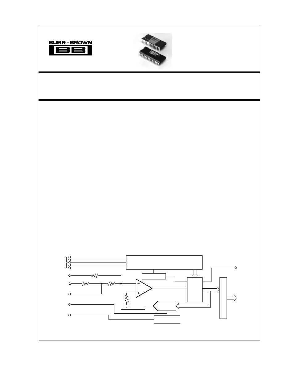
DESCRIPTION
The ADC574A is a 12-bit successive approximation
analog-to-digital converter, utilizing state-of-the-art
CMOS and laser-trimmed bipolar die custom-designed
for freedom from latch-up and for optimum AC per-
formance. It is complete with a self-contained +10V
reference, internal clock, digital interface for micropro-
cessor control, and three-state outputs.
The reference circuit, containing a buried zener, is laser-
trimmed for minimum temperature coefficient. The
clock oscillator is current-controlled for excellent sta-
bility over temperature. Full-scale and offset errors may
be externally trimmed to zero. Internal scaling resistors
are provided for the selection of analog input signal
ranges of 0V to +10V, 0V to +20V,
±
5V, and
±
10V.
The converter may be externally programmed to pro-
vide 8- or 12-bit resolution. The conversion time for 12
bits is factory set for 25
µ
s maximum.
Output data are available in a parallel format from TTL-
compatible three-state output buffers. Output data are
coded in straight binary for unipolar input signals and
bipolar offset binary for bipolar input signals.
The ADC574A, available in both industrial and military
temperature ranges, requires supply voltages of +5V
and
±
12V or
±
15V. It is packaged in a 28-pin plastic
DIP, and a hermetic side-brazed ceramic DIP.
International Airport Industrial Park · Mailing Address: PO Box 11400 · Tucson, AZ 85734 · Street Address: 6730 S. Tucson Blvd. · Tucson, AZ 85706
Tel: (520) 746-1111 · Twx: 910-952-1111 · Cable: BBRCORP · Telex: 066-6491 · FAX: (520) 889-1510 · Immediate Product Info: (800) 548-6132
Successive
Approximation
Register
Control Logic
Comparator
12-Bit D/A
Converter
10V
Control
Inputs
Bipolar
Offset
20V Range
10V Range
Reference
Input
Reference
Output
Three-State Buffers
Status
Parallel
Data
Output
Clock
Reference
© 1984 Burr-Brown Corporation
PDS-550G
Printed in U.S.A., August, 1993

2
®
ADC574A
SPECIFICATIONS
ELECTRICAL
At T
A
= +25
°
C, V
CC
= +12V or +15V, V
EE
= 12V or 15V, and V
LOGIC
= +5V unless otherwise specified.
ADC574AJP, JH, SH
ADC574AKP, KH, TH
PARAMETER
MIN
TYP
MAX
MIN
TYP
MAX
UNITS
RESOLUTION
12
*
Bits
INPUTS
ANALOG
Voltage Ranges: Unipolar
0 to +10, 0 to +20
*
V
Bipolar
±
5,
±
10
*
V
Impedance: 0 to +10V,
±
5V
4.7
5
5.3
*
*
*
k
±
10V, 0V to +20V
9.4
10
10.6
*
*
*
k
DIGITAL (CE, CS, R/C, A
O
, 12/8)
Over Temperature Range
Voltages: Logic 1
+2
+5.5
*
*
V
Logic 0
0.5
+0.8
*
*
V
Current
5
0.1
+5
*
*
*
µ
A
Capacitance
5
*
pF
TRANSFER CHARACTERISTICS
ACCURACY
At +25
°
C
Linearity Error
±
1
±
1/2
LSB
Unipolar Offset Error (Adjustable to Zero)
±
2
*
LSB
Bipolar Offset Error (Adjustable to Zero)
±
10
±
4
LSB
Full-Scale Calibration Error
(1)
(Adjustable to Zero)
±
0.25
*
% of FS
(2)
No Missing Codes Resolution (Diff. Linearity)
11
12
Bits
Inherent Quantization Error
±
1/2
*
LSB
T
MIN
to T
MAX
Linearity Error: J, K Grades
±
1
±
1/2
LSB
S, T Grades
±
1
±
3/4
LSB
Full-Scale Calibration Error
Without Initial Adjustment
(1)
: J, K Grades
±
0.47
±
0.37
% of FS
S, T Grades
±
0.75
±
0.5
% of FS
Adjusted to Zero at +25
°
C: J, K Grades
±
0.22
±
0.12
% of FS
S, T Grades
±
0.5
±
0.25
% of FS
No Missing Codes Resolution (Diff. Linearity)
11
12
Bits
TEMPERATURE COEFFICIENTS (T
MIN
to T
MAX
)
(3)
Unipolar Offset: J, K Grades
±
10
±
5
ppm/
°
C
S, T Grades
±
5
±
2.5
ppm/
°
C
Max Change: All Grades
±
2
±
1
LSB
Bipolar Offset: All Grades
±
10
±
5
ppm/
°
C
Max Change: J, K Grades
±
2
±
1
LSB
S, T Grades
±
4
±
2
LSB
Full-Scale Calibration: J, K Grades
±
45
±
25
ppm/
°
C
S, T Grades
±
50
±
25
ppm/
°
C
Max Change: J, K Grades
±
9
±
5
LSB
S, T Grades
±
20
±
10
LSB
POWER SUPPLY SENSITIVITY
Change in Full-Scale Calibration
+13.5V < V
CC
< +16.5V or +11.4V < V
CC
< + 12.6V
±
2
±
1
LSB
16.5V < V
EE
< 13.5V or 12.6V < V
EE
< 11.4V
±
2
±
1
LSB
+4.5V < V
LOGIC
< +5.5V
±
1/2
*
LSB
CONVERSION TIME
(4)
8-Bit Cycle
10
13
17
*
*
*
µ
s
12-Bit Cycle
15
20
25
*
·
·
µ
s
OUTPUTS
DIGITAL (DB
11
DB
0
, STATUS)
(Over Temperature Range)
Output Codes: Unipolar
Unipolar Straight Binary (USB)
Bipolar
Bipolar Offset Binary (BOB)
Logic Levels: Logic 0 (I
SINK
= 1.6mA)
+0.4
*
V
Logic 1 (I
SOURCE
= 500
µ
A)
+2.4
*
V
Leakage, Data Bits Only, High -Z State
5
0.1
+5
*
*
*
µ
A
Capacitance
5
*
pF

3
®
ADC574A
SPECIFICATIONS
(CONT)
ELECTRICAL
At T
A
= +25
°
C, V
CC
= +12V or +15V, V
EE
= 12V or 15V, and V
LOGIC
= +5V unless otherwise specified.
ADC574AJP, JH, SH
ADC574AKP, KH, TH
PARAMETERS
MIN
TYP
MAX
MIN
TYP
MAX
UNITS
* Same specifications as ADC574AJP, AJH, ASH.
NOTES: (1) With fixed 50
resistor from REF OUT to REF IN. This parameter is also adjustable to zero at
±
25
°
C (see Optional External Full Scale and Offset
Adjustments section). (2) FS in this specification table means Full Scale Range. That is, for a
±
10V input range, FS means 20V; for a 0 to +10V range, FS means
10V. The term Full Scale for these specifications instead of Full-Scale Range is used to be consistent with other vendors' 574 and 574A type specifications tables.
(3) Using internal reference. (4) See Controlling the ADC574A section for detailed information concerning digital timing. (5) External loading must be constant during
conversion. The reference output requires no buffer amplifier with either
±
12V or
±
15V power supplies.
PIN CONFIGURATION
+5VDC Supply (V )
12/8
CS
A
R/C
CE
+V
Ref Out
Analog Common
Ref In
V
Bipolar Offset
10V Range
20V Range
Status
DB11 (MSB)
DB10
DB9
DB8
DB7
DB6
DB5
DB4
DB3
DB2
DB1
DB0 (LSB)
Digital Common
1
2
3
4
5
6
7
8
9
10
11
12
13
14
28
27
26
25
24
23
22
21
20
19
18
17
16
15
LOGIC
CC
EE
5k
10k
10V
Reference
12-Bit
D/A
Converter
Successive Approximation Register
Control
Logic
Power-up Reset
Clock
12 Bits
Comparator
12 Bits
Nibble A
Nibble B
Nibble C
Three-State Buffers and Control
O
5k
INTERNAL REFERENCE VOLTAGE
Voltage
+9.9
+10.0
+10.1
*
*
*
V
Source Current Available for External Loads
(5)
2.0
*
mA
POWER SUPPLY REQUIREMENTS
Voltage: V
CC
+11.4
+16.5
*
*
V
V
EE
11.4
16.5
*
*
V
V
LOGIC
+4.5
+5.5
*
*
V
Current: I
CC
3.5
5
*
*
mA
I
EE
15
20
*
*
mA
I
LOGIC
9
15
*
*
mA
Power Dissipation (
±
15V Supplies)
325
450
*
*
mW
TEMPERATURE RANGE (Ambient: T
MIN
, T
MAX
)
Specifications: J, K Grades
0
+75
*
*
°
C
S, T Grades
55
+125
*
*
°
C
Storage
65
+150
*
*
°
C

4
®
ADC574A
LINEARITY
TEMPERATURE
ERROR MAX
MODEL
PACKAGE
RANGE
(T
MIN
TO T
MAX
)
ADC574AJP
Plastic DIP
0
°
C to +75
°
C
±
1LSB
ADC574AKP
Plastic DIP
0
°
C to +75
°
C
±
1/2LSB
ADC574AJH
Ceramic DIP
0
°
C to +75
°
C
±
1LSB
ADC574AKH
Ceramic DIP
0
°
C to +75
°
C
±
1/2LSB
ADC574ASH
Ceramic DIP
55
°
C to +125
°
C
±
1LSB
ADC574ATH
Ceramic DIP
55
°
C to +125
°
C
±
3/4LSB
BURN-IN SCREENING OPTION
See text for details.
ABSOLUTE MAXIMUM RATINGS
V
CC
to Digital Common ......................................................... 0V to +16.5V
V
EE
to Digital Common .......................................................... 0V to 16.5V
V
LOGIC
Digital Common .............................................................. 0V to +7V
Analog Common to Digital Common ....................................................
±
1V
Control Inputs (CE, CS, A
O
, 12/8, R/C)
to Digital Common .............................................. 0.5V to V
LOGIC
+0.5V
Analog Inputs (Ref In, Bipolar Offset, 10V
IN
)
to Analog Common ......................................................................
±
16.5V
20V
IN
to Analog Common ..................................................................
±
24V
Ref Out .......................................................... Indefinite Short to Common,
Momentary Short to V
CC
Max Junction Temperature ............................................................ +165
°
C
Power Dissipation ........................................................................ 1000mW
Lead Temperature (soldering,10s) ................................................. +300
°
C
Thermal Resistance,
JA
: Ceramic ................................................ 50
°
C/W
Plastic ................................................. 100
°
C/W
CAUTION: These devices are sensitive to electrostatic discharge.
Appropriate I.C. handling procedures should be followed.
BURN-IN SCREENING
Burn-in screening is available for both plastic and ceramic
package ADC574s. Burn-in duration is 160 hours at the
temperature (or equivalent combination of time and tem-
perature) indicated below:
Plastic "BI" models: +85
°
C
Ceramic "BI" models: +125
°
C
All units are 100% electrically tested after burn-in is com-
pleted. To order burn-in, add "BI" to the base model
number (e.g., ADC574AKP-BI).
PACKAGE DRAWING
MODEL
PACKAGE
NUMBER
(1)
ADC574AJP
Plastic DIP
215
ADC574AKP
Plastic DIP
215
ADC574AJH
Ceramic DIP
149
ADC574AKH
Ceramic DIP
149
ADC574ASH
Ceramic DIP
149
ADC574ATH
Ceramic DIP
149
NOTE: (1) For detailed drawing and dimension table, please see end of data
sheet, or Appendix D of Burr-Brown IC Data Book.
ORDERING INFORMATION
TEMPERATURE
BURN-IN TEMP
MODEL
PACKAGE
RANGE
(160 Hours)
ADC574AJP-BI
Plastic DIP
0
°
C to +75
°
C
+85
°
C
ADC574AKP-BI
Plastic DIP
0
°
C to +75
°
C
+85
°
C
ADC574AJH-BI
Ceramic DIP
0
°
C to +75
°
C
+125
°
C
ADC574AKH-BI
Ceramic DIP
0
°
C to +75
°
C
+125
°
C
ADC574ASH-BI
Ceramic DIP
55
°
C to +125
°
C
+125
°
C
ADC574ATH-BI
Ceramic DIP
55
°
C to +125
°
C
+125
°
C
The information provided herein is believed to be reliable; however, BURR-BROWN assumes no responsibility for inaccuracies or omissions. BURR-BROWN assumes
no responsibility for the use of this information, and all use of such information shall be entirely at the user's own risk. Prices and specifications are subject to change
without notice. No patent rights or licenses to any of the circuits described herein are implied or granted to any third party. BURR-BROWN does not authorize or warrant
any BURR-BROWN product for use in life support devices and/or systems.
PACKAGE INFORMATION

5
®
ADC574A
DISCUSSION OF
SPECIFICATIONS
LINEARITY ERROR
Linearity error is defined as the deviation of actual code
transition values from the ideal transition values. Ideal
transition values lie on a line drawn through zero (or minus
full scale for bipolar operation) and plus full scale. The zero
value is located at an analog input value 1/2LSB before the
first code transition (000
H
to 001
H
). The full-scale value is
located at an analog value 3/2LSB beyond the last code
transition (FFE
H
to FFF
H
) (see Figure 1).
FIGURE 1. ADC574A Transfer Characteristics Terminology.
out the range. Thus, every input code width (quantum) must
have a finite width. If an input quantum has a value of zero
(a differential linearity error of 1LSB), a missing code will
occur.
ADC574AKP, KN, KH and TH grades are guaranteed to
have no missing codes to 12-bit resolution over their re-
spective specification temperature ranges.
UNIPOLAR OFFSET ERROR
An ADC574A connected for unipolar operation has an
analog input range of 0V to plus full scale. The first output
code transition should occur at an analog input value 1/2
LSB above 0V. Unipolar offset error is defined as the
deviation of the actual transition value from the ideal value.
The unipolar offset temperature coefficient specifies the
change of this transition value versus a change in ambient
temperature.
BIPOLAR OFFSET ERROR
A/D converter specifications have historically defined bipo-
lar offset as the first transition value above the minus full-
scale value. The ADC574A specification, however, follows
the terminology defined for the 574 converter several years
ago. Thus, bipolar offset is located near the midscale value
of 0V (bipolar zero) at the output code transition 7FF
H
to
800
H
.
Bipolar offset error for the ADC574A is defined as the
deviation of the actual transition value from the ideal
transition value located 1/2LSB below 0V. The bipolar
offset temperature coefficient specifies the maximum change
of the code transition value versus a change in ambient
temperature.
FULL SCALE CALIBRATION ERROR
The last output transition (FFE
H
to FFF
H
) occurs for an
analog input value 3/2LSB below the nominal full-scale
value. The full-scale calibration error is the deviation of the
actual analog value at the last transition point from the ideal
value. The full-scale calibration temperature coefficient
specifies the maximum change of the code transition value
versus a change in ambient temperature.
POWER SUPPLY SENSITIVITY
Electrical specifications for the ADC574A assume the
application of the rated power supply voltages of +5V and
±
12V or
±
15V. The major effect of power supply voltage
BINARY (BIN) OUTPUT
INPUT VOLTAGE RANGE AND LSB VALUES
Analog Input Voltage Range
Defined as:
±
10V
±
5V
0 to +10V
0 to +20V
One Least Significant Bit (LSB)
FSR
20V
10V
10V
20V
2
n
2
n
2
n
2
n
2
n
n = 8
78.13mV
39.06mV
39.06mV
78.13mV
n =12
4.88mV
2.44mV
2.44mV
4.88mV
Output Transition Values
FFE
H
to FFF
H
+Full-Scale Calibration
+10V 3/2LSB
+5 3/2LSB
+10V 3/2LSB
+10V 3/2LSB
7FF
H
to 800
H
Midscale Calibration (Bipolar Offset)
0 1/2LSB
0 1/2LSB
+5V 1/2LSB
±
10V 1/2LSB
Full-Scale
Calibration
Error
Rotates
The
Line
Offset
Error
Shifts
The Line
(Bipolar
Offset
Transaction)
Midscale
(Bipolar
Zero)
FFF
H
FFE
H
FFD
H
802
H
801
H
800
H
7FF
H
7FE
H
001
H
000
H
002
H
Digital Output
1/2LSB
Zero
(Full Scale)
Zero
(Full-Scale
Calibration
Transition)
1/2LSB
3/2LSB
+Full-Scale
Calibration
Transition
+Full
Scale
Analog Input
TABLE I. Input Voltages, Transition Values, and LSB Values.
Thus, for a converter connected for biopolar operation and
with a full-scale range (or span) of 20V (
±
10V), the zero
value of 10V is 2.44mV below the first code transition
(000
H
to 001
H
at 9.99756V) and the plus full-scale value of
+10V is 7.32mV above the last code transition (FFE
H
to
FFF
H
at +9.99268) (see Table I).
NO MISSING CODES
(DIFFERENTIAL LINEARITY ERROR)
A specification which guarantees no missing codes requires
that every code combination to appear in a monotonically-
increasing sequence as the analog input is increased through-