
Data
sheet
www.bookham.com
Thinking optical solutions
10 Gb/s Coplanar PIN
Preamp Receiver
The module consists of a PIN photodetector, a low noise
preamplifier, a connectorized single-mode fibre pigtail and a
hermetic metal package with coplanar output. Optimized for
use in 10 Gb/s long haul applications, either as a discrete
device or within a transponder, using NRZ Modulation.
www.bookham.com
Thinking optical solutions
Features
· High sensitivity, -20.5dBm typical
· Surface mount MSA compliant
· Low capacitance high speed
InGaAs PIN detector
· Hermetically sealed
· Designed to exceed the
requirements of Bellcore
GR468-CORE
· Single mode fibre tail
· Compatible with AT10GC APD
Receiver
· Output stage limits at 800mV p-p
differential eliminating the need for
a post amplifier
· Low Power Consumption,
only 235mW

Parameter
Symbol
Min
Typ
Max
Unit
Optical sensitivity 2
23
-1 BER <10
-12
(4)
Sens
-20.5
-19
dBm
Optical overload 2
23
-1 BER <10
-12
Psat
+1
dBm
High frequency -3 dB corner (2)
f3 dB
8
9
GHz
Return loss S22 (400 KHz to 7 GHz)
-8
dB
PiN bias voltage
Vpd
5
V
Dark current
Id
10
nA
PIN responsivity (1)
R
0.7
0.8
A/W
Amplifier bias voltage
Vee
-5.2
V
Amplifier current consumption
lee
45
mA
Transimpedance gain (2,3,5)
TZG
1600
2200
3400
Ohms
Characteristics
TC = 25°C unless otherwise specified.
Notes: 1) Optical wavelength between 1525nm 1575nm.
2) Load impedance is 50
(AC coupled) with a return loss >20 dB,up to 20 GHz.
3) Excludes PIN responsivity.
4) Measured with 10 Gb/s NRZ PRBS data and no FEC.
5) Differential
Parameter
Symbol
Min
Max
Unit
Amplifier bias voltage
Vcc
-6
0
V
Operating temperature (1)
Top
-40
85
°C
Storage temperature (2)
Tstg
-40
85
°C
Optical input (3)
po
10
dBm
Fibre bend radius
35 mm
Maximum PIN bias voltage
Vpd
+7.5
V
Absolute Ratings
Notes (Absolute Ratings):1) The operating temperature is defined as the temperature of the module case.
2) The rating is referred to ambient temperature.
3) The optical level that causes no damage to the module. However, the electrical and optical
performance specified in this document may not be guaranteed.
Pin #
Symbol
Parameter
Pin #
Symbol
Parameter
1 GND
Case
ground
10
Out_P
Positive
output
2
Vpd
PIN bias voltage
11
GND
Case ground
3
NC
No connection
12
GND
Case ground
4
Vee
Amplifier Bias
13
FBIN
Offset feedback (if used)
5
NC
No connection
14
NC
No connection
6
GND
Case ground
15
NC
No connection
7
GND
Case ground
16
NC
No connection
8
Out_N
Negative output
17
GND
Case ground
9
GND
Case ground
Pinout Table
www.bookham.com
Thinking optical solutions
www.bookham.com
Thinking optical solutions
Circuit Schematic and Dimensions
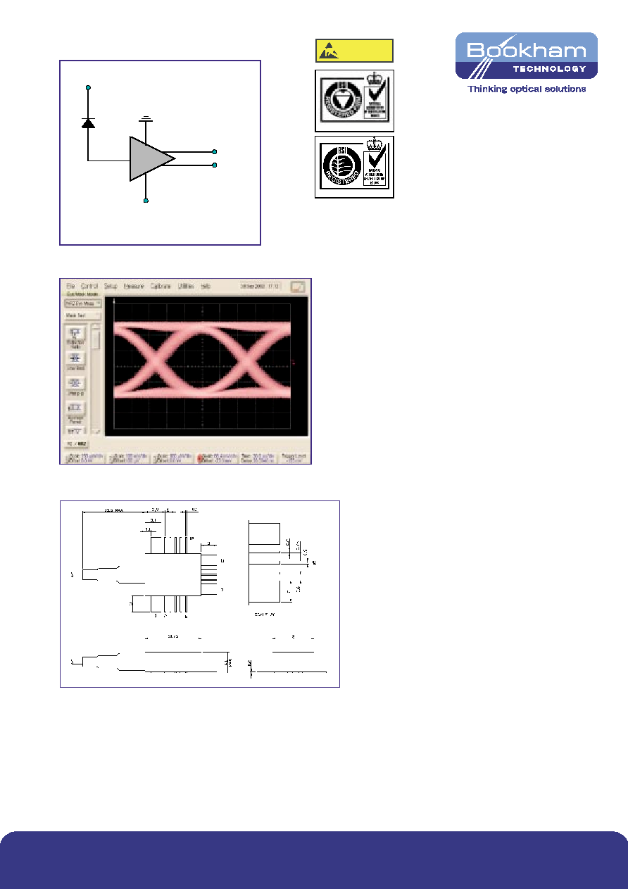
PT10XGC Schematic
Vpd
Out_N
Out_P
Vee (-5.2V)
CAUTION
STATIC SENSITIVE DEVICE
OBSERVE PRECAUTIONS
Certificate No. FM 15040
Certificate No. EMS 35100
Ordering Information
PT10XGC
Figure 2: Typical eye diagram measured at 10 Gb/s with NRZ data.
Figure 1: Schematic Diagram
Figure 3: Outline Diagram
www.bookham.com
REV 1 Feb 2003
© Bookham Technology 2003 Bookham & ASOC are registered trademarks of Bookham Technology plc
North America
Bookham Technology Inc.
49 Buford Highway
Suwanee
GA 30024
USA
· Tel: +1 678 482 4021
· Fax: +1 678 482 4022
Europe
Bookham Technology plc
Brixham Road
Paignton
Devon
TQ4 7BE
UK
· Tel: +44 (0) 1803 66 2875
· Fax: +44 (0) 1803 66 2801
Asia
Bookham Technology plc
21/F Cityplaza One
1111 King's Road
Quarry Bay
Hong Kong
· Tel: +852 (2100) 2249
· Fax: +852 (2100) 2585
Sales@bookham.com
Important Notice
Bookham Technology has a policy of
continuous improvement, as a result
certain parameters detailed on this flyer
may be subject to change without notice.
If you are interested in a particular product
please request the available from any
Bookham Technology sales representative.