
1
2150BBIOM09/03
Features
·
Sensitive Layer Over a 0.8 µm CMOS Array
·
Image Zone: 0.4 x 14 mm = 0.02" x 0.55"
·
Image Array: 8 x 280 = 2240 pixels
·
Pixel Pitch: 50 µm x 50 µm = 500 dpi
·
Pixel Clock: up to 2 MHz Enabling up to 1780 Frames per Second
·
Die Size: 1.7 x 17.3 mm
·
Operating Voltage: 3 V to 5.5 V
·
Naturally Protected Against ESD: > 16 kV Air Discharge
·
Power Consumption: 20 mW at 3.3 V, 1 MHz, 25°C
·
Operating Temperature Range: -40°C to +85°C
·
Resistant to Abrasion: >1 Million Finger Sweeps
·
Chip-on-Board (COB), Chip-on-Board (COB) with Connector, or 20-lead Ceramic DIP
Available for Development, with Specific Protective Layer
Applications
·
PDA (Access Control, Data Protection)
·
Cellular Phones, SmartPhones (Access e-business)
·
Notebook, PC-add on (Access Control, e-business)
·
PIN Code Replacement
·
Automated Teller Machines, POS
·
Building Access
·
Electronic Keys (Cars, Home,...)
·
Portable Fingerprint Imaging for Law Enforcement
·
TV Access
Figure 1. FingerChip
TM
Packages
Chip-on-Board Package
(COB)
Chip-on-Board Package
with connector
Actual size
Thermal
Fingerprint
Sensor with
0.4 mm x 14 mm
(0.02" x 0.55")
Sensing Area
and
Digital Output
(On-chip ADC)
AT77C101B
FingerChip
TM
Sweep your finger
to make life easier
Rev. 2150BBIOM09/03

2
AT77C101B FingerChip
TM
2150BBIOM09/03
The die attach is connected to pins 1, 7 and 21, and must be grounded. The FPL pin
must be grounded.
Table 1. Pin Description for Chip-on-Board Package: AT77C101B-CB01
Pin Number
Name
Type
1
GND
GND
2
AVE
Analog output
3
AVO
Analog output
4
TPP
Power
5
TPE
Digital input
6
VCC
Power
7
GND
GND
8
RST
Digital input
9
PCLK
Digital input
10
OE
Digital input
11
ACKN
Digital output
12
De0
Digital output
13
Do0
Digital output
14
De1
Digital output
15
Do1
Digital output
16
De2
Digital output
17
Do2
Digital output
18
De3
Digital output
19
Do3
Digital output
20
FPL
GND
21
GND
GND
1
2
3
4
5
6
7
8
9
10
11
12
13
14
15
16
17
18
19
20
21
GND
AVE
AVO
TPP
TPE
VCC
GND
RST
PCLK
OE
ACKN
De0
Do0
De1
Do1
De2
Do2
De3
Do3
FPL
GND

3
AT77C101B FingerChip
TM
2150BBIOM09/03
Note:
1. Ref Connector: FH18-21S-0.3SHW (HIROSE).
Table 2. Pin Description for COB with Connector Package: AT77C101B-CB02
(1)
Pin Number
Name
Type
1
FPL
GND
2
Not connected
3
Not connected
4
DE3
Digital output
5
DO3
Digital output
6
DE2
Digital output
7
DO2
Digital output
8
DE1
Digital output
9
DO1
Digital output
10
DE0
Digital output
11
DO0
Digital output
12
AVE
Analog output
13
AVO
Analog output
14
TPP
Power
15
TPE
Digital input
16
VCC
Power
17
GND
GND
18
RST
Digital input
19
PCLK
Digital input
20
OE
Digital input
21
ACKN
Digital output

4
AT77C101B FingerChip
TM
2150BBIOM09/03
Figure 2. COB with Flex
(1)
Figure 3. Flex Output Side
Note:
1. Flex is not provided by ATMEL.
Flex with metallizations up
Flex with metallizations down
2
3
1
Flex Output
(FingerChip Connector Side)
Metallizations Up
5
AT77C101B FingerChip
TM
2150BBIOM09/03
Description
The AT77C101B is part of the Atmel FingerChip monolithic fingerprint sensor family for
which no optics, no prism and no light source are required.
The AT77C101B is a single-chip, high-performance, low-cost sensor based on tempera-
ture physical effects for fingerprint sensing.
The AT77C101B has a linear shape, which captures a fingerprint image by sweeping
the finger across the sensing area. After capturing several images, Atmel proprietary
software can reconstruct a full 8-bit fingerprint image.
The AT77C101B has a small surface combined with CMOS technology, and a Chip-on-
Board package assembly. These facts contribute to a low-cost device.
The device delivers a programmable number of images per second, while an integrated
analog-to-digital converter delivers a digital signal adapted to interfaces such as an EPP
parallel port, a USB microcontroller or directly to microprocessors. No frame grabber or
glue interface is therefore necessary to send the frames. These facts make AT77C101B
an easy device to include in any system for identification or verification applications.
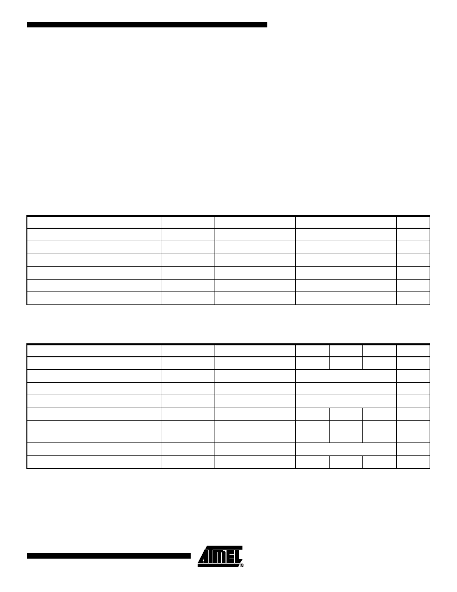
Note:
1. Absolute maximum ratings are limiting values, to be applied individually, while other parameters are within specified operat-
ing conditions. Long exposure to maximum ratings may affect device reliability.
Table 1. Absolute Maximum Ratings
(1)
Parameter
Symbol
Comments
Value
Unit
Positive supply voltage
V
CC
GND to 6.5
V
Temperature stabilization power
TPP
GND to 6.5
V
Front plane
FPL
GND to V
CC
V
Digital input voltage
RST PCLK
GND to V
CC
V
Storage temperature
T
stg
-50 to +95
°C
Lead temperature (soldering, 10 seconds)
T
leads
Do not solder
Forbidden
°C
Table 2. Recommended Conditions Of Use
Parameter
Symbol
Comments
Min
Typ
Max
Unit
Positive supply voltage
V
CC
3 V
5 V
5.5 V
V
Front plane
FPL
Must be grounded
GND
V
Digital input voltage
CMOS levels
V
Digital output voltage
CMOS levels
V
Digital load
C
L
50
pF
Analog load
C
A
R
A
Not connected
pF
k
Operating temperature range
T
amb
I grade
-40
°
C to +85
°
C
°C
Maximum current on TPP
ITPP
0
100
mA