
Data Sheet
AS2574B
Rev. 1
1
Jan. 1995
Package
Available in 28 pin DIP and PLCC.
20 NUMBER ONE TOUCH DIALLER WITH
SERIAL BUS FOR DISPLAY DRIVER
Austria Mikro Systeme International
Key Features
u
Low operating voltage (2.5V to 5.5V)
u
Low current consumption (typ. 200
µ
A in LD mode)
u
Oscillator using ceramic resonator (681 kHz)
u
MF level independent of supply voltage
u
Direct ´wake-up´ from keyboard
u
Automatic Call Progress by direct memory key
u
Data protection with 8 digit FIFO
u
Sliding cursor protocol with comparison
u
Diode options for different PTT requirements
u
Automatic pause generation after access code
u
Temporary MF select via keyboard
u
36 digit LNR (Last Number Redial)
u
20 memories addressable with direct keys and the
2nd key or indirect with a MEM key
u
Notepad
u
Serial interface to display driver AS2590
u
Consistent, simple and useable procedures
u
Input for dial tone recognizer
General Description
The AS2574B is an integrated CMOS device for feature
telephones. It is a very versatile LD/MF dialler with serial
interface to a display driver. The device is designed to be
used in a wide variety of applications together with the
companion display driver, AS2590.
The on chip RAM can contain up to 20 memories (each
with maximum 18 digits), a 36 digit Last Number Redial
(LNR) and an 18 digit notepad. Access to the 20 memo-
ries is either with direct keys, abbreviated dial code or a
combination of both. The AS2574B provides a unique
feature, Automatic Call Progress (ACP), on all memory
keys, i.e. the circuit automatically seizes the line and
waits for the dial tone and dials the number just by
pressing any of the memory keys (including LNR).
The circuit features 2 different access code procedures
to allow easy use under a PABX. A dial tone input
enables the use of a dial tone recognizer.
SDA
SCL
R5
C6
C5
C4
C3
C2
C1
V
DD
HS
TONE
DP
R1
R2
R3
R4
ER
Vss
TB
AS2574B
DIALLER/CONTROLLER
L a
Lb
E
LS
CD
MR
MT
M 4
M 8
M 7
M 6
M 5
M 2
M 1
M 3
MASK
OSC1
OSC2
681kHz
M U T E
R
E N T E R
2 N D
#
6
3
9
0
5
2
8
*
4
1
7
M 1 0
M E M
M 9
LNR
L S
SDA
SCL
V
DD
X1
X2
V23
V13
V
LCD
BIAS
MS
Vss
AS2590
32.768kHz
DISPLAY
MODE
ACP
M/B
MS
Flash
Ground
Loop
S P E E C H
LOUDHEARING
HANDSFREE
TONE RINGER
Application
High feature telephone sets.
Direct wake-up is an AMS patented
solution providing line seizing with
a telephone, that is entirely
powered from the telephone line,
by pressing a key in a key matrix
connected to a dialler/controller
that is constantly connected to the
line by means of a line voltage
limiter and yet maintaining a high
dc isolation resistance in idle state
(on-hook).
The wake-up feature allows the
user to go off-hook by pressing a
direct memory key or a
loudspeaker key, so-called on-
hook dialling or call progress
monitoring, and thereby seize the
line.
®

Data Sheet
AS2574B
Rev. 1
2
Jan. 1995
Pin #
Pin Node
Description
1
OSC2
Oscillator pins for ceramic resonator (681 kHz)
2
OSC1
3
SCL
The SCL output is used to clock all data into the display driver
4
SDA
The SDA output is used to transfer data into the display driver
5 - 10
C1 - 6
Keyboard columns
11 - 15
R1 - 5
Keyboard rows
16
LS
Output for controlling loudhearing and handsfree facilities, active high
(see hook state diagramme)
17
MASK
Mask output, active high during pulsing (make and break period, see timing
diagrammes).
18
CD
Chip disable input, active low.
When CD is low, the circiut is disabled.
If this pin is pulled to V
SS
during Off-hook (indicating a disconnect) for more than
2 sec., the circuit is reset*. If the pin is pulled to V
SS
for less than 2 sec., the
line break is ignored.
* If in ACP or monitor state, reset also means return to idle state.
19
MR
Mute output, active high during signalling (see timing diagrammes).
20
MT
Transmit mute output, active high when MR is high and when
the Mute key has been activated (see timing diagrammes).
21
ER
Earth recall input/output, active high during ER but when forced to V
DD
,
the flash is enabled.
22
DT
Dial tone input.
This input is scanned when invoking ACP or a pause is read in a digit string:
DT pin
Function
Open
Pause duration 4.1 sec
Low
If a high is not detected within 8 sec., the circuit is
reset *
High
If the pin is high for > 1.15 sec., the pause is termi-
nated and the dialling continued. Noise immunity > 8 ms
* Reset means that dialling is stopped and the circuit returns to standby.
If the circuit was in ACP state, the reset will also return the circuit to idle state.
23
DP
Hook switch control, dial pulse and flash output; low during Idle and break
periods and high during off-hook (see timing diagrammes).
Pin Description
Continues...

Data Sheet
AS2574B
Rev. 1
3
Jan. 1995
Pin Description Continued
Pin #
Pin Node
Description
24
HS
Hook switch input; active high with internal pull-down resistor. Debounce 25 ms.
25
Vss
Negative terminal of power supply.
26
TB
Tone burst output:
LS high
80 ms burst, 8 sec pause
MT high
80 ms burst, 2 sec pause
Only in speech mode
MT+LS high
80 ms burst, 2 sec pause
27
TONE
MF tone output.
An on chip reference voltage provides tone levels independent of the
supply voltage.
A dc path from TONE output is needed to accommodate an external voltage
divider for setting the appropriate tone level.
Frequencies:
Frequency (Hz)
Key Matrix (Hz)
Error (%)
697
row 1
770
row 2
852
row 3
941
row 4
1209
col. 1
±
0.7%
1336
col. 2
1477
col. 3
1633
see p. 7
28
Vdd
Positive terminal of power supply
RECALL
1
2
3
4
5
6
7
8
9
0
*
#
L S
LNR
M9
M1
M2
M3
M4
2ND
MUTE
M5
M6
M7
M8
COLUMN
1
2
3
4
5
6
ROWS
1
2
3
4
5
The keyboard is arranged in a 5 x 6 contact matrix with single pole single throw
contacts (SPST).
Keyboard resistance: Ron < 5 k
; Roff > 5 M
.
ENTER
MEM
M10
Enabled only
when off-hook
Enabled also
when ACP is
active (diode 5
inserted)
Enabled when
CD = high
In off-hook state all keys are
enabled (CD = high)
Keyboard Layout

Data Sheet
AS2574B
Rev. 1
4
Jan. 1995
Power On Reset
The on chip analogue power on reset circuit monitors the
supply voltage (V
DD
). As long as V
DD
remains below the
internal reference voltage, V
REF
(typically 1.2V), the
oscillator is inhibited. When V
DD
rises above V
REF
, a reset
signal is generated to assure correct start-up, and the
oscillator is enabled.
The correct start-up/reset condition of the circuit is
guaranteed regardless of the absolute and chronologi-
cal rise time of V
DD
, CD and HS inputs.
Line Supervision
In off-hook condition the device performs supervision of
the line current disconnects in the following manner:
Line disconnects (CD low) of less than 2 sec. are ignored
and the device continues operation.
Line disconnects of more than 2 sec. cause stop of
dialling and the circuit is switched to standby mode if HS
is high, otherwise the circuit will return to idle mode.
Mode Selection
The default mode (LD or MF) can be selected by the
diode option mode (diode 6).
When default LD mode is selected, a temporary change
to MF mode can be invoked by pressing the * key.
When the circuit is in temporary MF mode, each of the
Mute Key
Depressing the Mute key activates and deactivates
(toggle switch) the MT output, when internal mute is
inactive, i.e. when no data is being read from the RAM or
FIFO.
A change of the hook state will release the mute.
Valid Keys
A valid key is detected from the keyboard by connecting
the appropriate row to the column. This can be done
using an n x m keyboard matrix with single contacts.
Positive and negative edges of each contact are de-
bounced. The debounce time is 15 ms.
In idle state (on-hook) only the LS key is always valid
independent of the CD pin. When diode 5 is connected,
also the LNR, MEM, and M1 - 9 keys are valid entries
invoking ACP (automatic call progress).
following procedures revert it to default LD mode:
- pressing R key (all subsequently entered digits are
buffered in FIFO),
- by next On-hook.
Last Number Redial
LNR is a facility that allows resignalling of the last
manually dialled number without keying in all the digits
again. The LNR is repeatable.
A manually entered number is automatically stored in the
LNR RAM. The capacity of the RAM is 36 digits. If a
number greater than 36 digits is entered, the LNR facility
will be inhibited (until new entries < 37 digits) and further
entries will be buffered in FIFO. If more than 18 digits are
entered, the display will show the digit 19 and onwards.
Postdialled digits, i.e. digits manually entered after LNR
has been invoked, are not stored in RAM but buffered in
FIFO.
The current contents of the LNR RAM are overwritten by
new entries.
Memory Dial
An on chip RAM enables the dialler to store up to 20
numbers, each containing a maximum 18 digits/data.
The first 10 memories are accessible with 10 Direct dial
keys (M1 to M10) and another 10 memories (11 - 20) are
accessible by pressing the 2nd key before one of the
Direct dial keys or by pressing the MEM key and a digit
0 - 9 (abbreviated dialling).
Basic store procedure:
1 Press Enter key
2 Key in digits, including access code, pauses and recall
as appropriate (number is stored in LNR RAM)
3 Select location by keeping Enter key depressed while
entering the desired location (M1...M10, 2nd
M1...M10, or MEM 0...9)
4 Release Enter key to finish
5 Continue with 1, 2, 3 and 4 for storing further numbers.
Only the first 18 digits/data will be stored when copying
more than 18 digits/data in a memory.

Data Sheet
AS2574B
Rev. 1
5
Jan. 1995
Recall Function
A recall activation will invoke a flash (timed loop break)
or an earth recall (ER) depending on the ER pin. When
the ER pin is forced to V
DD
, a flash is executed; and when
ER is open (> 50 k
}, an earth recall is executed.
If R is the first entry in a digit string, it will be stored in LNR
RAM.
If the R key is depressed after a digit string has been
dialled out, the recall will not be stored, and subsequently
entered digits will be buffered in the FIFO.
A recall will automatically generate a pause when a recall
is read from a memory and therecall has been stored as
an access code.
A manual invoked earth recall will pull ER high for
minimum 500 ms, but the ER pin is maintained high as
long as the key is depressed.
During auto dial an earth recall is executed with a
duration of 500 ms.
Pause Generation
Pause introduces a delay in signalling digits strings to
accommodate second and subsequent dial tones.
Automatic pauses are generated:
- during dialling out from memories when the first digit(s)
in the digit string equal the stored access code(s)
(pause depends on DT input).
- when going Off-hook by pressing LNR, MEM, or M1 -
9 (ACP).
Any pause can be terminated (shortened) prior to time
out by pressing the LNR key or a high level on the DT
input.
During ACP a pause time out, i.e. DT kept low for > 8
sec., will return the device to idle state.
Pauses are storable as digits within a string of any of the
memories by pressing 2nd # during programming.
Multiple pause entries can be stored up to the maximum
length of the digit string (18 digits/data). A pause is not
accepted in location 1 of a digit string.
If more pauses have been stored in succession, they can
all be terminated by one depression of the LNR key or a
high level on the DT pin for
1.15 sec.
Sliding Cursor Procedure
To accommodate redialling (LNR) behind a PABX wi-
thout using automatic pause generation (storing access
codes), a sliding cursor protocol is implemented. If new
entries match the previous LNR RAM contents, pressing
the LNR key will dial out the remaining digits.
If there is an error in matching, the LNR will be inhibited
until next On-hook, and the LNR RAM will contain the
new number.
Access Codes
Different access codes (totally up to 18 digit/data inclu-
ding spaces) can be stored in one string. Spaces bet-
ween the different access codes are entered by pressing
the 2nd # during programming. Each access code can
contain up to 4 digits.
If one or more access codes are stored, the first entered
digit(s) in a digit string read from the RAM will be
compared with the access code(s) and if equal, a pause
is generated.
Example on programming access codes:
ENTER, 9 , 2nd #, 50
Keep
ENTER
depressed while pressing
0
Release both
The first access code in this example is 9 and the second
50.

Data Sheet
AS2574B
Rev. 1
6
Jan. 1995
No
Symbol/command
MSB
B3
B2
B1
LSB
HEX
1
0
1
1
1
0
0
1C
2
1
0
0
0
0
0
00
3
2
0
0
1
0
0
04
4
3
0
0
0
1
0
02
5
4
1
0
0
0
0
10
6
5
1
0
1
0
0
14
7
6
1
0
0
1
0
12
8
7
0
1
0
0
0
08
9
8
0
1
1
0
0
0C
10
9
0
1
0
1
0
0A
11
a
0
0
1
1
0
06
12
b
1
0
1
1
0
16
13
c
0
1
1
1
0
0E
14
d
1
1
1
1
0
1E
15
*
1
1
0
0
0
18
16
#
1
1
0
1
0
1A
17
Pause
1
1
0
1
1
1B
18
Temporary MF select
1
1
0
0
1
19
19
Recall
0
0
0
0
1
01
20
LS on
0
0
1
0
1
05
21
LS off
0
0
0
1
1
03
22
MT on
1
0
0
0
1
11
23
MT off
0
1
0
0
1
09
24
2nd on
0
0
1
1
1
07
25
2nd off
1
1
1
1
1
1F
26
Set Clock
0
1
0
1
1
0B
27
Start
0
1
1
0
1
0D
28
Start copy
0
1
1
1
1
0F
29
Start FIFO
1
0
0
1
1
13
30
Start timer
1
0
1
0
1
15
31
Blank all
1
1
1
0
1
1D
32
Test mode
1
0
1
1
1
17
Serial Interface
The AS2574B supports a serial bus. The protocol
defines device that sends data onto the bus as a
transmitter, and the receiving device as the receiver. The
AS2574B is controlling the transfer and hence the
master. The display driver, AS2590, being controlled is
the slave.
Clock and Data Conventions
Data states on the SDA line can change only during SCL
low. SDA state changes during SCL high are reserved
for indicating start and stop conditions (see figure 1).
Start Condition
All commands are preceded by the start condition, which
is a high to low transition of SDA when SCL is high.
Stop Condition
All communications are terminated by a stop condition,
which is low to high transition of SDA when SCL is high.
START
BIT
SDA
SCL
BIT 0
BIT 1 ...
... BIT 4
STOP BIT
WORD
GAP
Figure 1: Data Transmission

Data Sheet
AS2574B
Rev. 1
7
Jan. 1995
Key/Key Combination
Function
Remarks
ENTER
Programming
R
Flash or ground loop
Code no 19
MEM
Abbreviated dialling
MUTE
Privacy mute
Code no 22/23
LS
Monitor/Handsfree
Code no 20/21
LNR
Last Number Redial
During execution of a pause the LNR key is used
to terminate the pause.
M1 - 10
Direct memory keys
2nd
Second functions
Code no 24
2nd, 1
a
Code no 11
2nd, 2
b
Code no 12
2nd, 3
c
Code no 13
2nd, 4
d
Code no 14
2nd, *
Enter FIFO
Code no 29
2nd, #
Pause
Code no 17
2nd, M1 - 10
Memories 11 - 20
MEM, 0 - 9
Memories 11 - 20
ENTER, Address*
Displaying content of Memo
ENTER/Address*
Programming
Code no 28 when both keys are released
ENTER/#
Setting clock
Code no 26
2nd, 5 - 9
5 - 9
Code no 6 - 10
2nd, 0
0
Code no 1
2nd, R
RECALL
Code no 19
2nd, MUTE
Privacy MUTE
Code no 22/23
ENTER/LNR
Clearing LNR
Code no 27
ENTER, ENTER
Displaying Access code
Code no 27
*)
Address means M1 - 10 keys or 2nd, M1 - 10 or MEM, 0 -9 key combinations.
Key Combinations

Data Sheet
AS2574B
Rev. 1
8
Jan. 1995
Diode Options
System Considerations
The device is intended to be used in telephone instru-
ments, that are permanently on-line, i.e. also when on-
hook the circuit is connected to the telephone line, but in
standby mode (idle) and hence only drawing a small
leakage current from the line.
This implementation offers new features like electronic
hook switch and call progress monitoring (on-hook
dialling).
Call progress monitoring (CPM) means pressing the LS
key will switch the telephone on from standby (direct
´wake-up´from keyboard) and will present the dialling
tones via a loudspeaker without lifting the handset.
Furthermore, it is also possible to invoke the CPM by
pressing the LNR, MEM or M1 - 9 when the ACP
(Automatic Call Progress) is activated (diode 5).
Option
Column
Function
No diode
diode
NoP
1
Number of Pulses
Standard
NZ
Digit 1
1
9
2
2
8
3
3
7
4
4
6
5
5
5
6
6
4
7
7
3
8
8
2
9
9
1
0
10
10
FT
2
Flash Time
101.2 ms
600 ms
MS
3
Memory Size
10
20
M/B
4
Make/Break Ratio
33/66 ms
40/60 ms
ACP
5
Automatic Call Progress
no
yes
MODE
6
Default Signalling Mode
MF
LD
Procedure Principles
The procedures for utilizing the features of the device are
optimized out of consideration for the human factor
in order to:
- meet the user´s expectations
- be easy to learn and relearn
- not invoke any automatic functions which the user
doesn't expect
- protect the user from committing critical errors, e.g.
dialling wrong numbers, deleting stored numbers, etc.
- be consistent, simple and usable.
1
2
3
4
5
6
Columns
Row 5
MODE
ACP
M/B
MS
FT
NoP
The diode options
are scanned by
POR and low to
high transition on
HS.

Data Sheet
AS2574B
Rev. 1
9
Jan. 1995
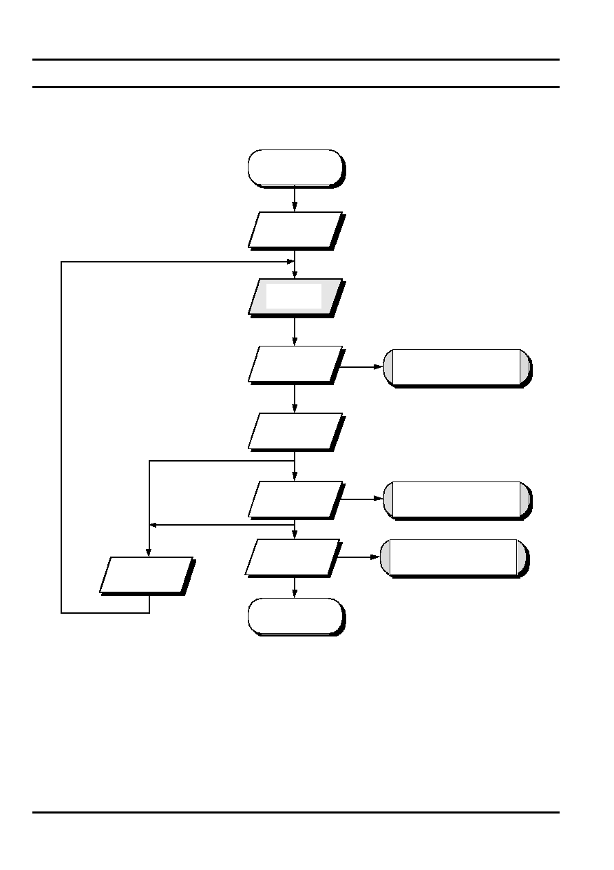
Manual Dial
Symbols
Idle
Idle
Standby state, no keys activated
Lifting handset (HS = High) or pressing LS key
Replacing handset (HS = Low) or repressing LS key
Off-hook
On-hook
Idle
Idle
Speech mode
Idle
Entries are
dialled out
The last manually dialled number is automatically stored in the LNR RAM.
In LD mode * invokes temporary MF mode and # are ignored.
In MF mode * and # are automatically stored in LNR RAM.
Off-hook
Key in
digits
Entries stored
in LNR RAM
On-hook

Data Sheet
AS2574B
Rev. 1
10
Jan. 1995
Programming/Notepad
Speech mode
or idle
Speech mode
or idle
Speech mode
During programming
the dial out is inhibited.
10 Direct dial keys, a MEM and a 2nd key are available for addressing up to 20 numbers.
Each number can contain up to 18 digits, including recall and pauses.
Programming a new number will automatically clear the previous.
2nd, # has to be pressed between the different access codes.
no
change
Digits are entered
in LNR RAM
The content of the LNR RAM
is stored in the selected memory.
Speech mode
Enter
Key in
number
keep Enter
depressed
Enter
Direct dial
(M1 - 10)
2nd
MEM
Digit 0
(access codes)
Digit 0-9
(M11 - 20)
Direct dial
(M11 - 20)
Access code(s)
are displayed
release
Enter
Code no 28
stored
Key in
an address
Content of selected
memory is displayed
Enter
correction

Data Sheet
AS2574B
Rev. 1
11
Jan. 1995
Direct Dial/Abbreviated Dial/Last Number Redial
Idle
N
Y
Y
N
Y
N
D
D
D
D
D
D
Off-hook
Diode
3 ?
Digit 0 - 9
(M11 - 20)
Direct dial
(M11 - 20)
MEM
2nd
Direct dial
(M1 - 10)
LNR
DIALLING
Pause
All digits
dialled ?
DT
pin
Executing pause
Starting timer
Speech mode
Postdialling
available
D
HS = High
Y
N
DT high
1.15 sec
Hi-Z
Pause
4 sec
H
L
Terminate pause
Reset timer
Timer
overflow
Y
N
Y
N

Data Sheet
AS2574B
Rev. 1
12
Jan. 1995
Automatic Call Progress (ACP)
Off-hook
Start timer
Off-hook
Start timer
Off-hook
Start timer
Speech mode
D
D
Y
D
D
N
Y
Off-hook
Start timer
D
Y
N
Y
N
Idle
Diode
3 ?
(Diode 5 inserted)
MEM
Direct dial
(M1 - 9)
LNR
Digit 0 - 9
(M11 - 20)
Time-out
8 sec
Reset timer
Dialling
Pause
All digits
dialled ?
Postdialling
available
DT
pin
Executing pause
Starting timer
DT high
1.15 sec
Hi-Z
Pause
4 sec
H
L
Terminate pause
Reset timer
Timer
overflow
Y
N
Y
N
Off-hook
Start timer
Off-hook
Start timer
N
Time-out
8 sec
N
Y

Data Sheet
AS2574B
Rev. 1
13
Jan. 1995
Privacy Mute
Speech mode
Speech mode
MT output will go low.
Speech mode
MT high
Dialling
MT output will go low.
(code 23)
(code 22)
(code 23)
Mute key
Change of
hook state
Mute key

Data Sheet
AS2574B
Rev. 1
14
Jan. 1995
Temporary MF Select
Speech mode
LD default
Speech mode
MF selected
LD default
Idle
All further entries are NOT stored in LNR
RAM but buffered in FIFO.
The LNR RAM will contain the number
entered before pressing the * key and
the mode change code.
*
Key in
digits
Recall
On-hook
Key in
digits
Off-hook
LD default
Speech mode
LD default
Data Sheet
AS2574B
Rev. 1
15
Jan. 1995
Setting Clock (in display driver)
Speech mode
or idle
keep Enter
depressed
Speech mode
or idle
Speech mode
keep Enter
depressed
Speech mode
or idle
__:__
18:__
18:31
Press
#
release
Enter
Key in hours
(2 digits)
Key in min.
(2 digits)
keep Enter
depressed
Enter
keep Enter
depressed
Enter

Data Sheet
AS2574B
Rev. 1
16
Jan. 1995
Hook States
LS
M
LS
LS
Idle
P O T
P O T
+
Monitor
On-hook
Off-hook
1)
2)
1) Pressing any unvalid key doesn´t have any effect in Idle state.
2) POT means Plain Ordinary Telephone.
3) Lift handset means HS going high.
4) Replace handset means HS going low.
5) Lifting the handset during ACP will change the hook state to POT, however, the dialling will continue uneffected.
Automatic
Call Progress
(ACP)
LS
Dialling
finished
N
Y
N
Y
( )
Diode
5 ?
5)
Monitor
or
Handsfree

Data Sheet
AS2574B
Rev. 1
17
Jan. 1995
Timing Diagrammes
The timing diagrammes do not show the correct scaling only the sequence.
CD
HS
< 2 sec.
2 sec.
DP
P.O.T.
Whole
keyboard
enabled
Diode scanning
CD
LS key
DP
< 2 sec.
2 sec.
Monitor State
Whole
keyboard
enabled
CD
LS key
DP
< 2 sec.
2 sec.

Data Sheet
AS2574B
Rev. 1
18
Jan. 1995
LD Dialling
MF Dialling
MR
Tpo
Tb
Tb
Osc
Mask
DP
Tidp
Tm
Tb
Tpo
Tidp
2
1
Key entry
MT
= depending on Mute key
(high when Mute key has been activated, otherwise low)
Tpre
Tpre
Tho
DP
3
Key entry
2
1
MT
Mask
Tone
Osc
Ttd Titp
MR
= depending Mute key
(high when Mute key has been activated, otherwise low)
Tmo
Tho
Tmo
Tho

Data Sheet
AS2574B
Rev. 1
19
Jan. 1995
Flash
Ground Loop (GL)
Pause
R
Osc
Key entry
MR
Mask
DP
GL
Tpo
MT
= depending on Mute key
(high when Mute key has been activated, otherwise low)
Tfd
T
ho
T
pre
Tpo
R
Tgl
GL
DP
Mask
MR
MT
Key entry
Osc
Pause
= depending on Mute key
(high when Mute key has been activated, otherwise low)
Tho
T
pre

Data Sheet
AS2574B
Rev. 1
20
Jan. 1995
Tone
MT
MR
Osc
Mask
DP
Key entry
= depending on Mute key
(high when Mute key has been activated, otherwise low)
LNR
GL
Pause
Tap
Automatic Dialling MF (content of LNR is Flash, 1, 2, 3, and Flash is stored as access code)
Tmo
Tpo
MT
MR
Osc
Mask
DP
Key entry
= depending on Mute key
(high when Mute key has been activated, otherwise low)
LNR
GL
Pause
Tap
Automatic Dialling LD (content of LNR is GL, 2, 1 and GL is stored as access code)
Tidp
Tpo
Tho

Data Sheet
AS2574B
Rev. 1
21
Jan. 1995
Parameter
Symbol
Min
Typ
Max
Unit
Condition
Supply Current
I
DD
Outputs unloaded
Operating except MF
200
250
µ
A
Operating MF
0.75
1
mA
Data Retention
1
2
µ
A
V
DD
=1.8V; note1
2
4
µ
A
Note 1
Input Voltage
Low
Vil
V
SS
0.3xV
DD
V
High
Vih
0.7xV
DD
V
DD
V
Input Current
Low
Iil
1
µ
A
High
Iih
1
µ
A
Output Current
Sink
Iol
1.5
mA
Vol = 0.4V
Source
Ioh
1
mA
Voh = V
DD
- 0.4V
Pull-down Resistor
HS Input
Rhs
1
M
CD Input
Rcd
1
M
Scanning Current DT
During Pause
Sink
Isl
20
150
µ
A
Source
Ish
20
150
µ
A
Parameter
Symbol
Min
Typ
Max
Unit
Condition
Operating Temperatur
Top
- 25
70
°
C
Operating Voltage
V
DD
2.5
3.0
5.5
V
Retention Voltage
V
DD
1.8
5.5
V
Oscillator Frequency
Fosc
681
kHz
Electrical Data
Absolute Maximum Ratings
Recommended Operating Range
DC Characteristics
Default conditions: Recommended Operating Range; V
DD
= 3.0V.
Note 1: Circuit in Idle state (HS = Low and no key activated).
Positive Supply Voltage ...................................................................................................................-0.3V
V
LS
7V
Input Voltage .......................................................................................................................-0.3V
V
IN
V
DD
+ 0.3V
Input Current ................................................................................................................................................
±
25 mA
Storage Temperature ......................................................................................................................-65
°
C to +125
°
C
Electrostatic Discharge (HBM) ......................................................................................................................
±
1000V

Data Sheet
AS2574B
Rev. 1
22
Jan. 1995
Parameter
Symbol
Min
Typ
Max
Unit
Condition
Clock Startup Time
Ts
5
ms
Key Debounce Time
Td
14
18
ms
HS Debounce Time
Ths
21
26
ms
CD Reset Delay Time
Tr
2
sec
DTMF
Tone Level, High Group
Vol
- 12.4
- 10.9
- 9.4
dBm
RL = 15 k
Preemphasis
2
2.5
2.8
dBm
RL = 15 k
Distortion
- 26
dBr
RL = 15 k
, note 3
Tone Duration
Ttd
80
82.3
85
ms
Note 1
Inter Tone Pause
Titp
80
82.3
85
ms
Note 1
Tone Rise/Fall Time
Ttr
5
ms
Note 2
LD
Dial Rate
10
pps
±
5%
Make/Break Period
Tm/Tb
33/66
ms
±
5%
(diode option)
40/60
ms
±
5%
Inter Digit Pause
Tidp
753
785
ms
Pre Digit Pause
Tpre
55
57
ms
Post Digit Pause
Tpo
55
57
ms
Flash
Duration
Tfd
100
101.2
103
ms
No diode 2
600
620
ms
With diode 2
Earth Recall
Tg
Duration
500
510
ms
Automatic Access Pause
Tap
Short
4
4.1
4.2
sec
DT = Hi-Z
Long
7.9
8
8.1
sec
DT = Low
Termination
1.15
1.2
1.25
sec
DT = High
Mute Overhang
Tmo
182
200
223
ms
MR/MT Hold Over
Tho
18
27
ms
Tone Burst
Frequency
Fb
700
800
Hz
Output Level
Vtb
-13
-11
-9
dBm
Tone Duration
Ttb
80
85
ms
Inter Tone Pause (LS)
Titb1
7
8
9
sec
Inter Tone Pause (Mute)
Titp2
1.8
2
2.2
sec
Time-out
Tto
7.7
8
8.2
sec
Signalling Characteristics
Defaults conditions: Recommended Operating Range
Note 1: The values are valid during automatic dialling and are minimum values during manual dialling, i.e. the tones will continue
as long as the key is depressed.
Note 2: The rise time is the time from valid key detection (key has been debounced) till the tone amplitude has reached 90 % of its
final value.
Note 3: Relative to high group.

Data Sheet
AS2574B
Rev. 1
23
Jan. 1995
Pin Configuration
28 Pin DIP
28 Pin SOIC
28 Pin PLCC
1
28
14
15
Vdd
TONE
TB
Vss
HS
DP
DT
ER
MT
R1
MR
CD
MASK
LS
OSC2
OSC1
SCL
SDA
C1
C2
C3
C6
C4
C5
R2
R3
R4
R5
1
28
OSC2
OSC1
SCL
SDA
C1
C2
C3
C6
C4
C5
R2
R3
R4
R5
Vdd
TONE
TB
Vss
HS
DP
DT
ER
MT
R1
MR
CD
MASK
14
15
LS
C1
C2
C3
C6
C4
C5
MR
Vss
HS
DP
DT
ER
MT
R1
SDA
SCL
OSC1
OSC2
Vdd
TONE
TB
R3
R4
R5
LS
MASK
CD
R2
Ordering Information
Part number
Package
AS2574B P
28 pin DIL
AS2574B N
28 pin PLCC

Data Sheet
AS2574B
Rev. 1
24
Jan. 1995
Copyright
©
1995, Austria Mikro Systeme International, Schloss Premstätten, 8141 Unterpremstätten, Austria. Trademarks
Registered
®
. All rights reserved. The material herein may not be reproduced, adapted, merged, translated, stored, or used without
the prior written consent of the copyright owner.
Devices sold by Austria Mikro Systeme are covered by the warranty and patent indemnification provisions appearing in its Term of
Sale. Austria Mikro Systeme makes no warranty, express, statutory, implied, or by description regarding the information set forth
herein or regarding the freedom of the described devices from patent infringement. Austria Mikro Systeme reserves the right to
change specifications and prices at any time and without notice. Therefore, prior to designing this product into a system, it is necessary
to check with Austria Mikro Systeme for current information. This product is intended for use in normal commercial applications.
Applications requiring extended temperature range, unusual environmental requirements, or high reliability applications, such as
military, medical life-support or life-sustaining equipment are specifically
not recommended without additional processing by Austria
Mikro Systeme for each application.