Äîêóìåíòàöèÿ è îïèñàíèÿ www.docs.chipfind.ru
ATS672LSB
Preliminary Subject to Change
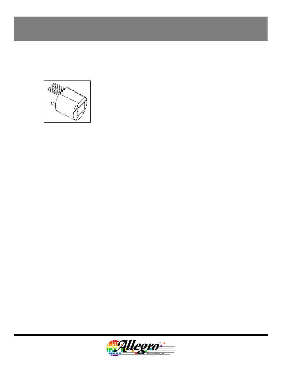
PIN OUT DIAGRAM
Self-Calibrating TPO Gear-Tooth Sensor with
9-Bit Signal Capture
4 3 2 1
Pin 1: V
CC
Pin 2: V
OUT
Pin 3: Test Pin (Tie to GND)
Pin 4: Gnd
The ATS672LSB true zero-speed gear-tooth sensors are
optimized Hall IC/magnet configurations packaged in a single in-
line package (SIP) that provides a user-friendly solution for digital
gear-tooth-sensing applications. The SIP module consists of an
over-molded package, which holds together a samarium cobalt
magnet, a pole piece and a true zero-speed Hall IC that has been
optimized to the magnetic circuit. This small package can be
easily assembled and used in conjunction with gears of various
shapes and sizes.
The sensor incorporates a single-element Hall IC that switches
in response to magnetic signals created by a ferrous target. The
IC contains a sophisticated digital circuit designed to eliminate the
detrimental effects of magnet and system offsets. Signal
processing is used to provide zero-speed performance
independent of air gap and also to dynamically adapt device
performance to the typical operating conditions found in
automotive applications (reduced vibration sensitivity). High-
resolution (9-bit) peak-detecting DACs are used to set the adaptive
switching thresholds of the device. Hysteresis in the thresholds
reduces the negative effects of any anomalies in the magnetic
signal (such as magnetic overshoot).
The ATS672LSB also includes a low-bandwidth filter that
increases the noise immunity and the signal-to-noise ratio of the
sensor. These features result in potential improvements in both
the timing accuracy and the jitter performance of the device. The
ATS672LSB sensor system is optimized for cam applications.
Four versions of this device are available. The sensor can be
chosen to have a high or low output signal in response to a "tooth".
The sensor is also available with and without TPOS (true power on
state) capability. The low-on-tooth sensor without TPOS is
available through general sales. (Part # ATS672LSB-LN). For
other versions please contact the factory. Some restrictions may
apply.
ABSOLUTE MAXIMUM RATINGS
Supply Voltage,
V
CC
. . . . . . . . . . . . . . . . . . . . . . . . . . 28 V
Reverse Supply Voltage,
V
R
. . . . . . . . . . . . . . . . . . . . . . . . . . . . 18 V
Reverse Current Through Output,
I
R
. . . . . . . . . . . . . . . . . . . . . . . . . . . . 50 mA
Continuous Output Current,
I
OUT
. . . . . . . . . . . . . . . . . . . . . . . . . . 20 mA
Storage Temperature,
T
S
. . . . . . . . . . . . . . . . . . . . . . . . . . . 170
° C
Package Power Rating,
R
JA
. . . . . . . . . . . . . . . . . . . ~150
°C/W
Maximum Junction Temperature,
T
Jmax
. . . . . . . . . . . . . . . . . . . . . . . . . 170
° C
Maximum Junction Temperature 100 Hours,
T
Jmax
. . . . . . . . . . . . . . . . . . . . . . . . . 180
° C
FEATURES
Tight timing accuracy over temperature
True zero-speed operation
True power-on sensing
Air gap independent switch points
High vibration immunity
Large operating air gaps
Operation down to 3.3 V
Digital output representing target profile
Single-chip solution for high reliability
Small mechanical size
Optimized Hall IC magnetic system
AGC and reference-adjust circuit
Undervoltage lockout
ATS672LSB
SELF-CALIBRATING TPOS GEAR-TOOTH SENSOR WITH 9-BIT SIGNAL CAPTURE
Preliminary Subject to Change
Rev. 1.2 May 1, 2002
Page 2 of 12
115 Northeast Cutoff, Box 15036
Worcester, Massachusetts 01615-0036 (508) 853-5000
Copyright © 1993, 1995 Allegro MicroSystems, Inc.
OPERATING CHARACTERISTICS
Valid at T
A
= -40°C to +150°C and power supply within specification unless
otherwise noted
Limits
Characteristics Symbol
Test
Conditions
Min. Typ. Max. Units
ELECTRICAL CHARACTERISTICS
Supply Voltage
V
CC
Operating;
T
J
< T
J
max 3.3
26.5
V
Reverse Supply Voltage
V
RCC
I
RCC
= -5 mA (max)
-18
V
Supply Zener Clamp Voltage
V
Z
28
33
37
V
Supply Zener Current
I
Z
Tj < Tjmax; pulsed
100
mA
Output = off
3.0
6.5
11
mA
Supply Current
I
CC
Output = on
3.0
6.5
11
mA
POWER-ON STATE CHARACTERISTICS
Power Up Time
t
PO
Gear Speed < 100 rpm; Vcc> 3.3 V
-
500
µs
Under Voltage Lockout
V
UV
-
<Vcc
Min
V
OUTPUT STAGE
Low Output Voltage
V
OUT
I
OUT
= 15 mA, Output = on
-
0.2
0.45
V
Output Current Limit
I
lin
Output = ON, Tj < Tjmax
25
45
70
mA
Output Leakage Current
I
OFF
Output = off, V
OUT
= Vcc
(Max)
-
10
µA
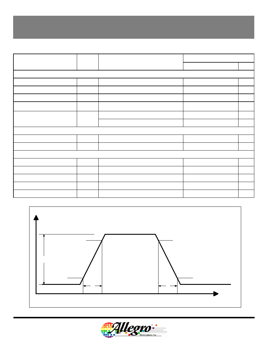
Output Rise Time
t
r
R
L
= 500
, C
L
= 10 pF, T
A
= 25°C
- 0.9 5.0
µs
Output Fall Time
t
f
R
L
= 500
, C
L
= 10 pF, T
A
= 25°C
- 0.5 5.0
µs
Time
[Seconds]
Output High
Output Low
100%
Rise and Fall Time
10%
90%
t
r
90%
10%
t
f
ATS672LSB
SELF-CALIBRATING TPOS GEAR-TOOTH SENSOR WITH 9-BIT SIGNAL CAPTURE
Preliminary Subject to Change
Rev. 1.2 May 1, 2002
Page 3 of 12
115 Northeast Cutoff, Box 15036
Worcester, Massachusetts 01615-0036 (508) 853-5000
Copyright © 1993, 1995 Allegro MicroSystems, Inc.
Limits
Characteristics Symbol
Test
Conditions
Min. Typ. Max. Units
SWITCH POINT CHARACTERISTICS
Tooth Speed
S
max
0
8.0
kHz
Bandwidth
f-3db
40 kHz
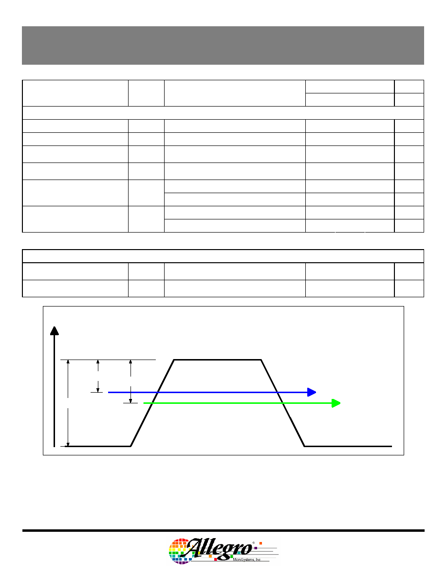
Operate Point
Bop%
% of peak to peak referenced to tooth
signal, AG < Agmax;
+30 %
Release Point
Brp%
% of peak to peak referenced to tooth
signal, AG < Agmax;
+40 %
Over
valley
HIGH
Output Polarity
ATS672LSB-LN (no TPOS)
ATS672LSB-LT (with TPOS)*
V
OUT
Over tooth
LOW
Over valley
LOW
Output Polarity
ATS672LSB-HN (no TPOS)*
ATS672LSB-HT (with TPOS)*
V
OUT
Over
tooth
HIGH
* Restrictions on availability may apply.
Calibration
Initial Calibration
C
I
Number of rising mechanical edges for
accurate edge detection
3
Edges
AGC Disable
C
f
Number of rising mechanical edges
required to complete AGC calibration
3
Edges
Tooth Signal
Valley Signal
100%
Brp%
Bop%
Brp%
Bop%
Switchpoints

ATS672LSB
SELF-CALIBRATING TPOS GEAR-TOOTH SENSOR WITH 9-BIT SIGNAL CAPTURE
Preliminary Subject to Change
Rev. 1.2 May 1, 2002
Page 4 of 12
115 Northeast Cutoff, Box 15036
Worcester, Massachusetts 01615-0036 (508) 853-5000
Copyright © 1993, 1995 Allegro MicroSystems, Inc.
OPERATION WITH 8X Reference Target over Operational Air Gap and Temperature with Test Circuit #1 Unless
Otherwise Stated
Limits
Characteristics Symbol
Test
Conditions
Min. Typ. Max. Units
t
ICRel
Rising and falling edge, RPM = 1000
during initial calibration
gear eccentricity < 0.1 mm
3.0
6.0 °
t
Rel
Rising mechanical edge
after initial calibration, RPM = 1000
gear eccentricity < 0.1 mm
- 0.3 0.6 °
1
Relative Timing Accuracy
t
Rel
Falling mechanical edge
after initial calibration, RPM = 1000
gear eccentricity < 0.1 mm
- 0.5 0.8 °
t
AbsRise
Rising mechanical edge
air gap: 1.5mm, temperature: 25°C
RPM: 1000
- -0.2 - °
2
Absolute Timing Accuracy
t
AbsFall
Falling mechanical edge
air gap: 1.5mm, temperature: 25°C
RPM: 1000
- +0.6 - °
3
Phase Delay
t
RelSpeed
After initial calibration
air gap: 1.5 mm, temperature: 25°C
- 6.66 -
x 10
-5
°
/ RPM
4
TPOS Air Gap Min
ATS672LSB LT and HT
AG
Min
Valleys may be detected as teeth:
incorrect TPOS
- - 0.5
mm
5
TPOS Air Gap Range
ATS672LSB LT and HT
AG
TPOS
Distance for correct TPOS functionality
0.5
-
2.25
mm
6
TPOS Air Gap Max
ATS672LSB LT and HT
AG
Max
Teeth may be detected as a valley:
incorrect TPOS
2.25 - 5.0 mm
Operational Air Gap Range
AG
Output switching: running mode only
0.5
-
2.25
mm
Edge Repeatability
t
E
360° repeatability, 1000 edges
0.04
°
1
Relative Timing Accuracy Range is the change in edge position over the operational air gap and temperature range that
can be expected from a single device. This does not include part-to-part variation.
2
The Typical Absolute Timing Accuracy is the difference between the target mechanical edge (rising or falling) and the
corresponding sensor electrical edge.
3
Phase Delay is the change in edge position over the operational RPM range that can be expected from a single device.
This does not include part-to-part variation or variation due to temperature.
4
The TPOS Air Gap Min is the Installation Air Gap where the device may detect Valleys as Teeth. The True Power On
Function is NOT guaranteed to operate.
5
The TPOS Air Gap Range is the Installation Air Gap Range where the True Power On Function is guaranteed to
operate. Operating is defined as correctly detecting a tooth when powered up over a tooth and correctly detecting a valley
when powered up over a valley using the Reference Target. This specification is only valid for targets that meet or
exceed the `Gear Parameters for Correct TPOS Operation' section of this document.
6
The TPOS Air Gap Max is the Installation Air Gap where the device may detect a Tooth as a Valley. The True Power On
Function is NOT guaranteed to operate.
ATS672LSB
SELF-CALIBRATING TPOS GEAR-TOOTH SENSOR WITH 9-BIT SIGNAL CAPTURE
Preliminary Subject to Change
Rev. 1.2 May 1, 2002
Page 5 of 12
115 Northeast Cutoff, Box 15036
Worcester, Massachusetts 01615-0036 (508) 853-5000
Copyright © 1993, 1995 Allegro MicroSystems, Inc.
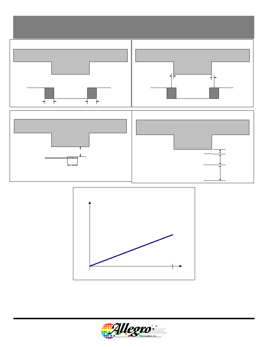
Target
Relative Timing Accuracy
Device Output
T
AbsRise
(Max - Min)
T
AbsFall
(Max - Min)
Tooth
Operational Air Gap
Valley
Air Gap
Target
Absolute Timing Accuracy
Device Output
T
AbsRise
T
AbsFall
T
AbsFall
(Max - Min)
Phase Delay with RPM
RPM
Phase Delay [°]
0
Max RPM
Tooth
TPOS Air Gap
Valley
TPOS Air Gap
Min
TPOS Air Gap
Range
TPOS Air Gap
Max