Äîêóìåíòàöèÿ è îïèñàíèÿ www.docs.chipfind.ru
ATS625LSG
ATS625LSG-DS, Rev. 1
Worcester, Massachusetts 01615-0036 (508) 853-5000
115 Northeast Cutoff, Box 15036
www.allegromicro.com
Allegro MicroSystems, Inc.
AB SO LUTE MAX I MUM RAT INGS
Supply Voltage
*
, V
CC
.......................................26.5 V
Reverse-Supply Voltage, V
RCC
........................18 V
Reverse-Supply Current, I
RCC
........................50 mA
Reverse-Output Voltage, V
ROUT
.....................0.5 V
Continuous Output Current, I
OUT
...................25 mA
Output Sink Current, I
OUT
............................. 10 mA
Operating Temperature
Ambient,
T
A
, Range L................ 40ºC to 150ºC
Maximum
Junction,
T
J(max)
........................165ºC
Maximum
Junction
100 hr, T
J(max100)
......180ºC
Storage Temperature, T
S
.................. 65ºC to 170ºC
*See the
Power Derating
section.
Highly repeatable over operating temperature range
Tight timing accuracy over operating temperature range
True zero-speed operation
Air-gapindependent switchpoints
Vibration immunity
Large operating air gaps
Defined power-on state
Wide operating voltage range
Digital output representing target profile
Single-chip sensing IC for high reliability
Small mechanical size
Optimized Hall IC magnetic system
Fast start-up
AGC and reference adjust circuit
Undervoltage lockout
The ATS625 true zero-speed gear tooth sensor is an optimized Hall IC and magnet
configuration packaged in a molded module that provides a manufacturer-friendly
solution for digital gear tooth sensing applications. The sensor assembly consists
of an over-molded package that holds together a samarium cobalt magnet, a
pole piece concentrator, and a true zero-speed Hall IC that has been optimized
to the magnetic circuit. This small package can be easily assembled and used in
conjunction with gears of various shapes and sizes.
The sensor incorporates a dual-element Hall IC that switches in response to
differential magnetic signals created by a ferrous target. Digital processing of the
analog signal provides zero-speed performance independent of air gap as well
as dynamic adaptation of device performance to the typical operating conditions
found in automotive applications (reduced vibration sensitivity). High-resolution
peak detecting DACs are used to set the adaptive switching thresholds of the
device. Switchpoint hysteresis reduces the negative effects of any anomalies in the
magnetic signal associated with the targets used in many automotive applications.
This sensor system is optimized for crank applications that utilize targets that
possess signature regions.
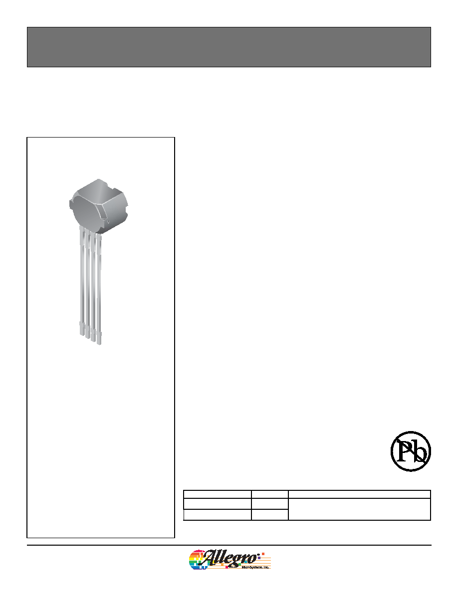
TheATS625 is provided in a 4-pin SIP. The Pb (lead) free option, available by
special request, has a 100% matte tin plated leadframe.
True Zero-Speed Low-Jitter
High Accuracy Gear Tooth Sensor
Features and Benefits
Package SG, 4-pin Through Hole
1. VCC
2. VOUT
3. AUX
4. GND
1
2
3
4
Part Number
Pb-free
Packing
1
ATS625LSGTN
Tape and Reel 13-in. 800 pcs./reel
ATS625LSGTN-T
Yes
2
1
Contact Allegro for additional packing options.
2
Available by special request only.
Use the following complete part numbers when ordering:
2
ATS625LSG-DS, Rev. 1
Worcester, Massachusetts 01615-0036 (508) 853-5000
115 Northeast Cutoff, Box 15036
www.allegromicro.com
Allegro MicroSystems, Inc.
True Zero-Speed Low-Jitter High Accuracy Gear Tooth Sensor
ATS625LSG
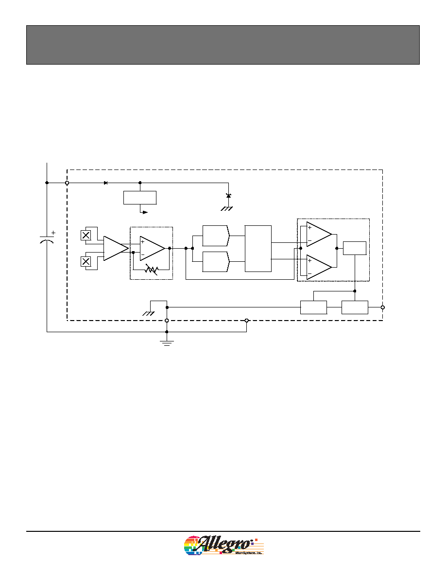
Functional Block Diagram
GND
VOUT
VCC
PPeak
Output
Transistor
Current
Limit
0.1 F
C
BYPASS
V+
Voltage
Regulator
AUX
Hall
Amp
Automatic
Gain
Control
V
PROC
PDAC
NDAC
Reference
Generator
NPeak
PThresh
NThresh
Threshold
Logic
Threshold
Comparator
(Recommended)

3
ATS625LSG-DS, Rev. 1
Worcester, Massachusetts 01615-0036 (508) 853-5000
115 Northeast Cutoff, Box 15036
www.allegromicro.com
Allegro MicroSystems, Inc.
True Zero-Speed Low-Jitter High Accuracy Gear Tooth Sensor
ATS625LSG
ELECTRICAL CHARACTERISTICS
Supply Voltage
V
CC
Operating; T
J
< T
Jmax
4.0
24
V
Undervoltage Lockout
V
CCUV
< V
CC(min)
V
Reverse Supply Current
I
RCC
V
CC
= 18 V
10
mA
Supply Zener Clamp Voltage
1
V
Z
I
CC
= 17 mA
28
V
Supply Zener Current
2
I
Z
V
S
= 28 V
17
mA
Supply Current
I
CC
Output OFF
8.5
14
mA
Output ON
8.5
14
mA
POWER-ON CHARACTERISTICS
Power-On State
S
PO
High
V
Power-On Time
t
PO
Gear Speed < 100 RPM; V
CC
> V
CC
min
200
µs
OUTPUT STAGE
Low Output Voltage
V
OUT(SAT)
I
SINK
= 20 mA, Output = ON
200
450
mV
Output Current Limit
I
OUT(LIM)
V
OUT
= 12 V, T
J
< T
Jmax
25
45
70
mA
Output Leakage Current
I
OUT(OFF)
Output = OFF, V
OUT
= 24 V
10
µA
Output Rise Time
t
r
R
L
= 500 , C
L
= 10 pF
1.0
2
µs
Output Fall Time
t
f
R
L
= 500 , C
L
= 10 pF
0.6
2
µs
SWITCHPOINT CHARACTERISTICS
Speed
S
Reference target 60+2
0
12000
rpm
Bandwidth
BW
Corresponds to switching frequency 3 dB
20
kHz
Operate Point
B
OP
% of peak-to-peak signal, AG < AG
max
;
B
IN
transitioning from LOW to HIGH
60
%
Release Point
B
RP
% of peak-to-peak signal, AG < AG
max
;
B
IN
transitioning from HIGH to LOW
40
%
CALIBRATION
Initial Calibration
3
Cal
PO
Start-up
1
6
edges
Calibration Update
Cal
Running mode operation
continuous
Operating Characteristics
Valid at T
A
= 40°C to 150°C, T
J
T
J(max)
, over full range of AG, unless otherwise noted; typical
operating parameters: V
CC
= 12 V and T
A
= 25°C
Characteristic
Symbol
Test Conditions
Min.
Typ.
Max.
Units
Continued on the next page...

4
ATS625LSG-DS, Rev. 1
Worcester, Massachusetts 01615-0036 (508) 853-5000
115 Northeast Cutoff, Box 15036
www.allegromicro.com
Allegro MicroSystems, Inc.
True Zero-Speed Low-Jitter High Accuracy Gear Tooth Sensor
ATS625LSG
OPERATING CHARACTERISTICS with 60+2 reference target
Operational Air Gap
AG
Measured from sensor branded face to
target tooth
0.5
2.5
mm
Relative Timing Accuracy, Sequen-
tial Mechanical Rising Edges
ERR
RR
Relative to measurement taken at
AG = 1.5 mm
±0.4
deg.
Relative Timing Accuracy, Sequen-
tial Mechanical Falling Edges
ERR
FF
Relative to measurement taken at
AG = 1.5 mm
±0.4
deg.
Relative Timing Accuracy, Signa-
ture Mechanical Rising Edge
4
ERR
SIGR
Relative to measurement taken at
AG = 1.5 mm
±0.4
deg.
Relative Timing Accuracy, Signa-
ture Mechanical Falling Edge
5
ERR
SIGF
Relative to measurement taken at
AG = 1.5 mm
±1.5
deg.
Relative Repeatability, Sequential
Rising and Falling Edges
6
T
E
360° Repeatability, 1000 edges; peak-peak
sinusoidal signal with B
PEAK
B
IN(min)
and
6° period
0.08
deg.
Operating Signal
7
B
IN
AG
(min)
< AG < AG
(max)
60
G
1
Test condition is I
CC(max)
+ 3 mA.
2
Upper limit is I
CC(max)
+ 3 mA.
3
Power-on speed 200 rpm. Refer to the Sensor Description section for information on start-up behavior.
4
Detection accuracy of the update algorithm for the first rising mechanical edge following a signature region can be adversely affected by the magnetic
bias of the signature region. Please consult with Allegro field applications engineering for aid with assessment of specific target geometries.
5
Detection accuracy of the update algorithm for the falling edge of the signature region is highly dependent upon specific target geometry. Please consult
with Allegro field applications engineering for aid with assessment of specific target geometries.
6
The repeatability specification is based on statistical evaluation of a sample population.
7
Peak-to-peak magnetic flux strength required at Hall elements for complying with operational characteristics.
Operating Characteristics, continued
Valid at T
A
= 40°C to 150°C, T
J
T
J(max)
, over full range of AG, unless otherwise noted;
typical operating parameters: V
CC
= 12 V and T
A
= 25°C
Characteristic
Symbol
Test Conditions
Min.
Typ.
Max.
Units
5
ATS625LSG-DS, Rev. 1
Worcester, Massachusetts 01615-0036 (508) 853-5000
115 Northeast Cutoff, Box 15036
www.allegromicro.com
Allegro MicroSystems, Inc.
True Zero-Speed Low-Jitter High Accuracy Gear Tooth Sensor
ATS625LSG
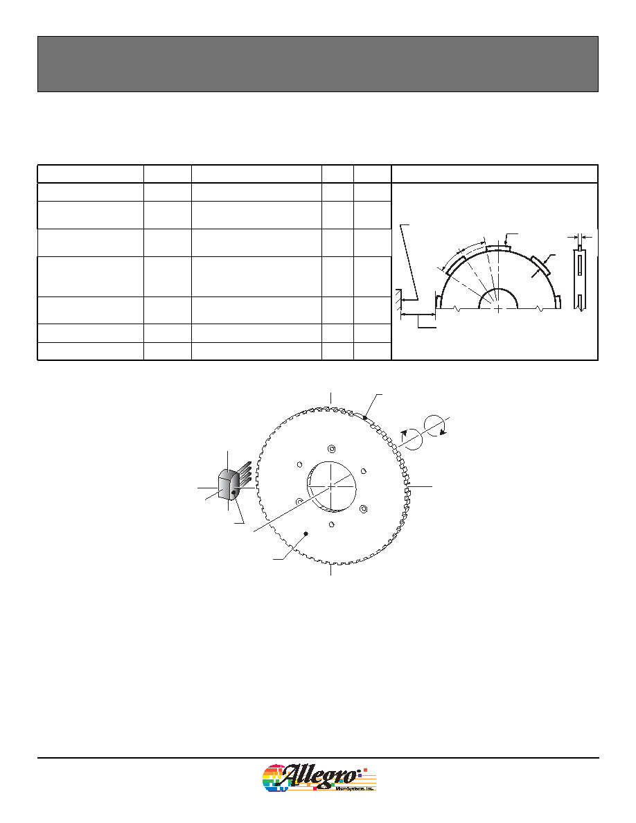
REFERENCE TARGET 60+2
Characteristics
Symbol
Test Conditions
Typ.
Units
Symbol Key
Outside Diameter
D
o
Outside diameter of target
120
mm
t,t
SIG
t
V
Ø
D
O
h
t
F
Branded Face
of Sensor
Air Gap
Face Width
F
Breadth of tooth, with respect
to sensor
6
mm
Circular Tooth Length
t
Length of tooth, with respect
to sensor; measured at D
o
3
mm
Signature Region Cir-
cular Tooth Length
t
SIG
Length of signature tooth,
with respect to sensor; mea-
sured at D
o
15
mm
Circular Valley Length
t
v
Length of valley, with respect
to sensor; measured at D
o
3
mm
Tooth Whole Depth
h
t
3
mm
Material
Low Carbon Steel
Reference Target
Signature Region
60+2
of Sensor
Branded Face
Pin 4
Pin 1
Reference Target (Gear) Information
For the generation of adequate magnetic field levels, the fol-
lowing recommendations should be followed in the design and
specification of targets:
· 2 mm < tooth width, t < 4 mm
· Valley width, t
v
> 2 mm
· Valley depth, h
t
> 2 mm
· Tooth thickness, F 3 mm
· Target material must be low carbon steel
Although these parameters apply to targets of traditional
geometry (radially oriented teeth with radial sensing, shown in
figure 1), they also can be applied in applications using stamped
targets (an aperture or rim gap punched out of the target mate-
rial) and axial sensing. For stamped geometries with axial sens-
ing, the valley depth, h
t
, is intrinsically infinite, so the criteria for
tooth width, t, valley width, t
v
, tooth material thickness, F, and
material specification need only be considered for reference. For
example, F can now be < 3 mm.
Figure 1. Configuration with Spur Gear Reference Target