HEDS-9000 (8 pg)
Two Channel Optical
Incremental Encoder Modules
Technical Data
Features
· High Performance
· High Resolution
· Low Cost
· Easy to Mount
· No Signal Adjustment
Required
· Small Size
· -40
°
C to 100
°
C Operating
Temperature
· Two Channel Quadrature
Output
· TTL Compatible
· Single 5 V Supply
Description
The HEDS-9000 and the HEDS-
9100 series are high performance,
low cost, optical incremental
encoder modules. When used with
a codewheel, these modules
detect rotary position. The
modules consist of a lensed (LED)
source and a detector IC enclosed
in a small C-shaped plastic
package. Due to a highly col-
limated light source and unique
photodetector array, these
modules are extremely tolerant to
mounting misalignment.
The two channel digital outputs
and the single 5 V supply input
are accessed through five 0.025
inch square pins located on 0.1
inch centers.
Standard resolutions for the
HEDS-9000 are 500 CPR and
1000 CPR for use with a HEDS-
6100 codewheel or equivalent.
ESD WARNING: NORMAL HANDLING PRECAUTIONS SHOULD BE TAKEN TO AVOID STATIC DISCHARGE.
HEDS-9000
HEDS-9100
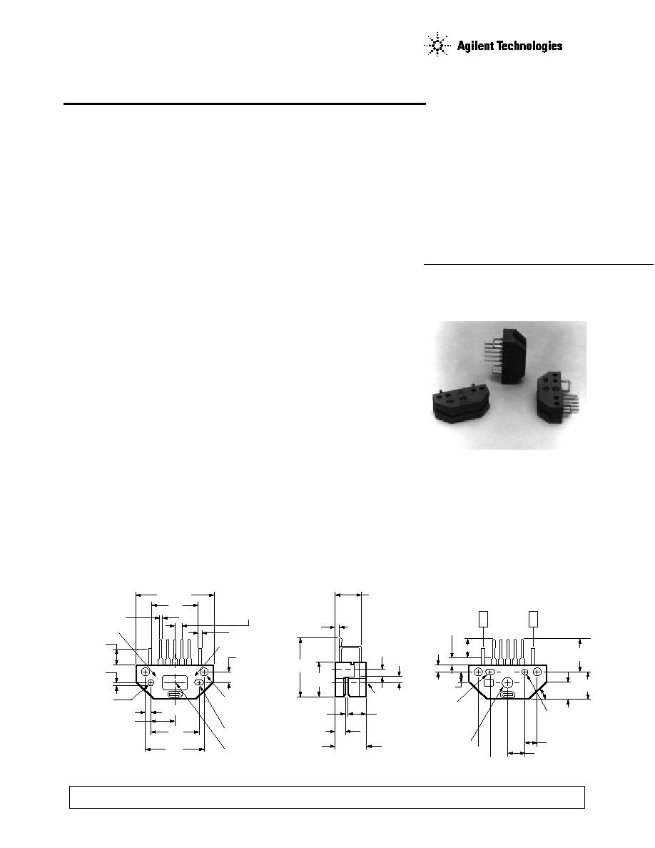
Package Dimensions
26.67 (1.05)
HEDS-9X00
15.2
(0.60)
CL
17.27
(0.680)
20.96
(0.825)
1.85 (0.073)
8.64 (0.340)
REF.
ALIGNING RECESS
2.44/2.41 DIA.
(0.096/0.095)
2.16 (0.085)
DEEP
1.02 ± 0.10
(0.040 ± 0.004)
5.1 (0.20)
X00
YYXX
OPTION CODE
0.63 (0.025)
SQR. TYP.
2.54 (0.100) TYP.
DATE CODE
1.0 (0.04)
3.73 ± 0.05
(0.147 ± 0.002)
2.67 (0.105) DIA.
MOUNTING THRU
HOLE 2 PLACES
2.44/2.41 X 2.79
(0.096/0.095 X 0.110)
2.16 (0.085) DEEP
OPTICAL CENTER
1.52 (0.060)
20.8
(0.82)
11.7
(0.46)
8.6 (0.34)
1.78 ± 0.10
(0.070 ± 0.004)
2.92 ± 0.10
(0.115 ± 0.004)
10.16
(0.400)
5.46 ± 0.10
(0.215 ± 0.004)
OPTICAL
CENTER LINE
2.54
(0.100)
2.21
(0.087)
5.8
(0.23)
6.35 (0.250) REF.
ALIGNING RECESS
2.44/2.41 X 2.79
(0.096/0.095 X 0.110)
2.16 (0.085) DEEP
4.11 (0.162)
ALIGNING RECESS
2.44/2.41 DIA.
(0.096/0.095)
2.16 (0.085) DEEP
OPTICAL
CENTER
45°
8.81
(0.347)
11.9
(0.47)
4.75 ± 0.10
(0.187 ± 0.004)
2.9
(0.11)
1.8
(0.07)
6.9 (0.27)
V
CC
GND
5 CH. B
4 V
CC
3 CH. A
2 N.C.
1 GND
SIDE A
SIDE B
TYPICAL DIMENSIONS IN
MILLIMETERS AND (INCHES)
2
For the HEDS-9100, standard
resolutions between 96 CPR and
512 CPR are available for use
with a HEDS-5120 codewheel or
equivalent.
Applications
The HEDS-9000 and 9100
provide sophisticated motion
detection at a low cost, making
them ideal for high volume
applications. Typical applications
include printers, plotters, tape
drives, and factory automation
equipment.
Note: Agilent Technologies
encoders are not recommended
for use in safety critical
applications. Eg. ABS braking
systems, power steering, life
support systems and critical care
medical equipment. Please
contact sales representative if
more clarification is needed.
Theory of Operation
The HEDS-9000 and 9100 are C-
shaped emitter/detector modules.
Coupled with a codewheel, they
translate the rotary motion of a
shaft into a two-channel digital
output.
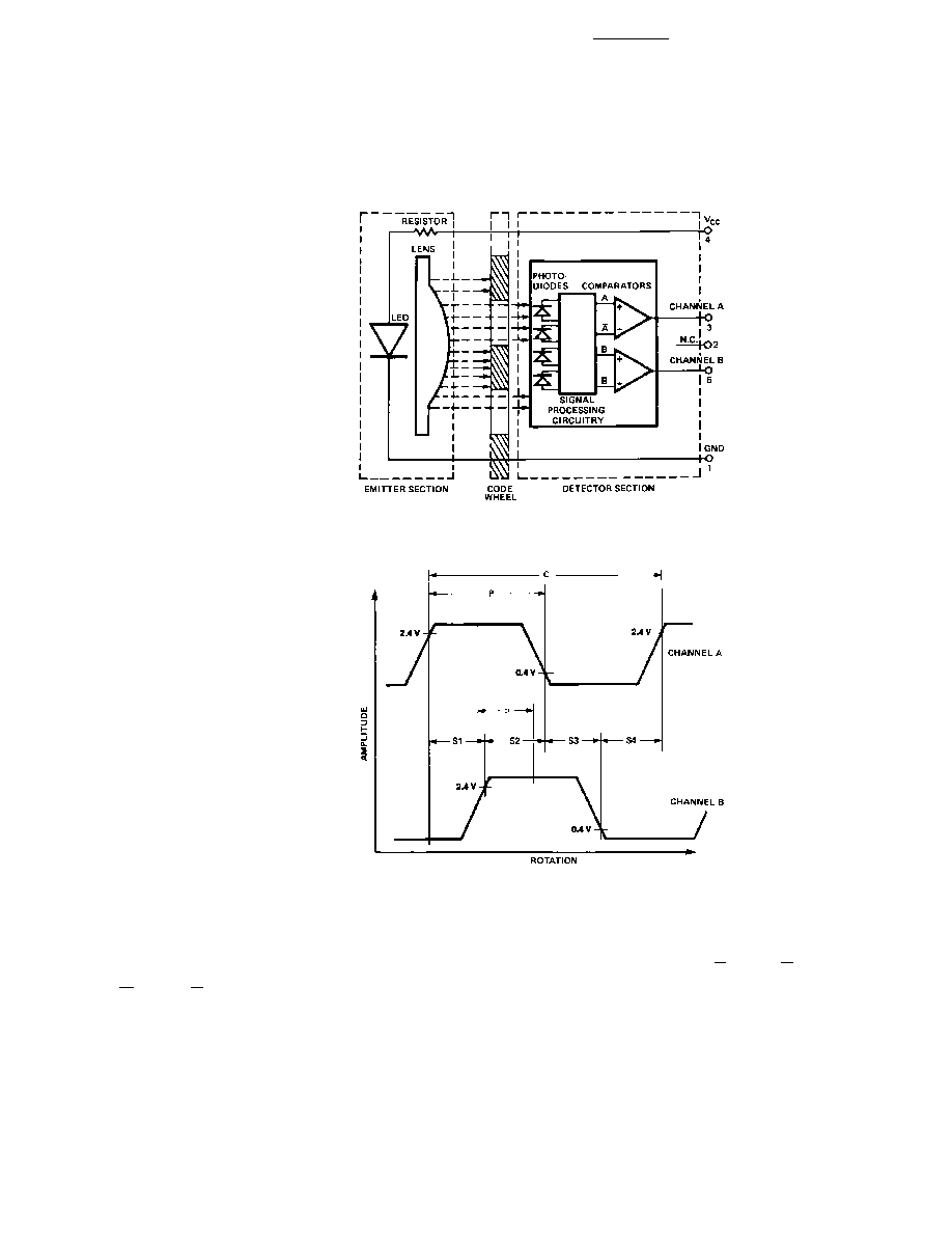
As seen in the block diagram,
each module contains a single
Light Emitting Diode (LED) as its
light source. The light is
collimated into a parallel beam by
means of a single polycarbonate
lens located directly over the
LED. Opposite the emitter is the
integrated detector circuit. This
IC consists of multiple sets of
photodetectors and the signal
processing circuitry necessary to
product the digital waveforms.
The codewheel rotates between
the emitter and detector, causing
the light beam to be interrupted
Block Diagram
by the pattern of spaces and bars
on the codewheel. The
photodiodes which detect these
interruptions are arranged in a
pattern that corresponds to the
radius and design of the ode-
wheel. These detectors are also
spaced such that a light period on
one pair of detectors corresponds
to a dark period on the adjacent
pair of detectors. The photodiode
outputs are then fed through the
signal processing circuitry
resulting in A, A, B, and B. Two
comparators receive these signals
and produce the final outputs for
channels A and B. Due to this
integrated phasing technique, the
digital output of channel A is in
quadrature with that of channel B
(90 degrees out of phase).
Output Waveforms
3
Absolute Maximum Ratings
Storage Temperature, T
S .....................................................................
-40
°
C to 100
°
C
Operating Temperature, T
A ................................................................
-40
°
C to 100
°
C
Supply Voltage, V
CC ......................................................................................
-0.5 V to 7 V
Output Voltage, V
O ........................................................................................
-0.5 V to V
CC
Output Current per Channel, I
out .................................................
-1.0 mA to 5 mA
Definitions
Count (N):
The number of bar
and window pairs or counts per
revolution (CPR) of the
codewheel.
1 Shaft Rotation = 360
mechanical
degrees,
= N cycles.
1 cycle (C) = 360
electrical
degrees (
°
e),
= 1 bar and
window pair.
Pulse Width (P): The number of
electrical degrees that an output
is high during 1 cycle. This value
is nominally 180
°
e or 1/2 cycle.
Pulse Width Error (
P):
The
deviation, in electrical degrees of
the pulse width from its ideal
value of 180
°
e.
State Width (S):
The number of
electrical degrees between a
transition in the output of channel
A and the neighboring transition
in the output of channel B. There
are 4 states per cycle, each
nominally 90
°
e.
State Width Error (
S):
The
deviation, in electrical degrees, of
each state width from its ideal
value of 90
°
e.
Phase (
):
The number of elec-
trical degrees between the center
of the high state of channel A and
the center of the high state of
channel B. This value is nominally
90
°
e for quadrature output.
Phase Error (
):
The deviation
of the phase from its ideal value
of 90
°
e.
Direction of Rotation:
When the
codewheel rotates in the direction
of the arrow on top of the
module, channel A will lead
channel B. If the codewheel
rotates in the opposite direction,
channel B will lead channel A.
Optical Radius (R
op
):
The dis-
tance from the codewheel's center
of rotation to the optical center
(O.C.) of the encoder module.
Recommended Operating Conditions
Parameter
Symbol
Min.
Typ.
Max.
Units
Notes
Temperature
T
-40
100
°
C
Supply Voltage
V
CC
4.5
5.5
Volts
Ripple < 100 mV
p-p
Load Capacitance
C
L
100
pF
3.3 k
pull-up resistor
Count Frequency
f
100
kHz
Velocity (rpm) x N
60
Note: The module performance is guaranteed to 100 kHz but can operate at higher frequencies.
Encoding Characteristics
Encoding Characteristics over Recommended Operating Range and Recommended Mounting Tolerances.
These Characteristics do not include codewheel/codestrip contribution.
Description
Sym.
Typ.
Case 1 Max.
Case 2 Max.
Units
Notes
Pulse Width Error
P
30
40
°
e
Logic State Width Error
S
30
40
°
e
Phase Error
2
10
105
°
e
Case 1: Module mounted on tolerance circle of
±
0.13 mm (
±
0.005 in.).
Case 2: HEDS-9000 mounted on tolerances of
±
0.50 mm (0.020").
HEDS-9100 mounted ontolerances of
±
0.38 mm (0.015").
4
Electrical Characteristics
Electrical Characteristics over Recommended Operating Range, typical at 25
°
C.
Parameter
Symbol
Min.
Typical
Max.
Units
Notes
Supply Current
I
CC
17
40
mA
High Level Output Voltage
V
OH
2.4
Volts
I
OH
= -40
µ
A max.
Low Level Output Voltage
V
OL
0.4
Volts
I
OL
= 3.2 mA
Rise Time
t
r
200
ns
C
L
= 25 pF
Fall Time
t
f
50
ns
R
L
= 11 k
pull-up
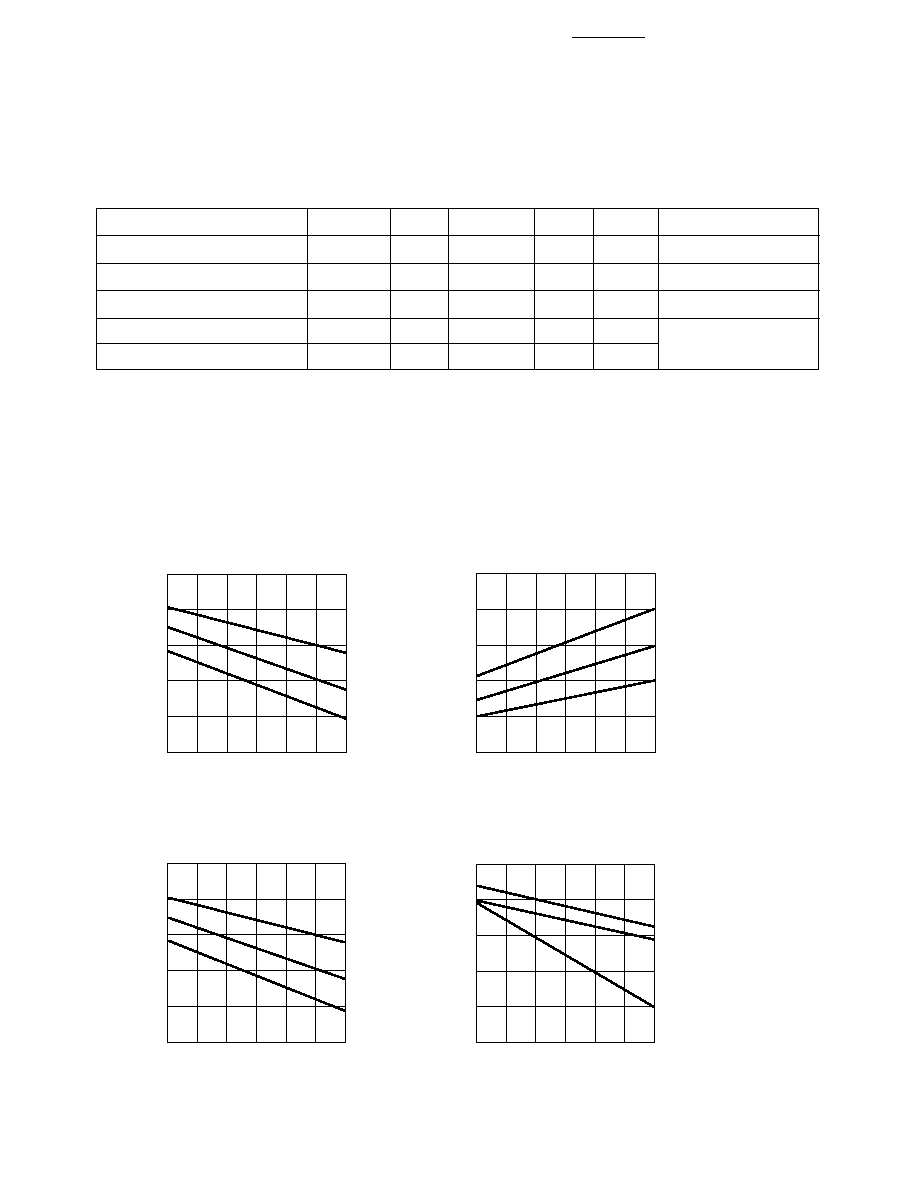
Derating Curves over Extended Operating Frequencies (HEDS-9000/9100)
Below are the derating curves for state, duty, phase and V
OH
over extended operating frequencies of up to
240 kHz (recommended maximum frequency is 100 kHz). The curves were derived using standard TTL load.
40
°
C operation is not feasible above 160 kHz because V
OH
will drop below 2.4 V (the minmum TTL for logic
state high) beyond that frequency.
120
220
FREQUENCY (kHz)
-40
0
CHANGE IN PULSE WIDTH ERROR
(ELECTRICAL DEGREE)
240
-30
-20
160
-10
140
200
180
100°C
25°C
-40°C
-50
120
220
FREQUENCY (kHz)
10
50
CHANGE IN STATE WIDTH ERROR
(ELECTRICAL DEGREE)
240
20
30
160
40
140
200
180
100°C
25°C
-40°C
0
120
220
FREQUENCY (kHz)
-10
0
CHANGE IN PHASE ERROR
(ELECTRICAL DEGREE)
240
-5
160
140
200
180
100°C
25°C
-40°C
120
220
FREQUENCY (kHz)
3
5
CHANGE IN V
OH
(VOLTS)
240
4
160
140
200
180
100°C
25°C
-40°C
2
1
0
5
Recommended Codewheel Characteristics
Figure 1. Codestrip Design
Codewheel Options
Optical
HEDS
CPR
Radius
Series
(N)
Option
mm (in.)
5120
96
K
11.00 (0.433)
5120
100
C
11.00 (0.433)
5120
192
D
11.00 (0.433)
5120
200
E
11.00 (0.433)
5120
256
F
11.00 (0.433)
5120
360
G
11.00 (0.433)
5120
400
H
11.00 (0.433)
5120
500
A
11.00 (0.433)
5120
512
I
11.00 (0.433)
6100
500
A
23.36 (0.920)
6100
1000
B
23.36 (0.920)
Parameter
Symbol
Minimum
Maximum
Units
Notes
Window/Bar Ratio
w
/
b
0.7
1.4
Window Length
L
W
1.8 (0.071)
2.3 (0.09)
mm (inch)
Absolute Maximum
R
C
R
OP
+ 1.9 (0.0075)
mm (inch)
Includes eccentricity
Codewheel Radius
errors
Document Outline