Three Channel Optical
Incremental Encoder Modules
Technical Data
HEDS-9040
HEDS-9140
Features
· Two Channel Quadrature
Output with Index Pulse
· Resolution Up to 2000 CPR
Counts Per Revolution
· Low Cost
· Easy to Mount
· No Signal Adjustment
Required
· Small Size
· -40
°
C to 100
°
C Operating
Temperature
· TTL Compatible
· Single 5 V Supply
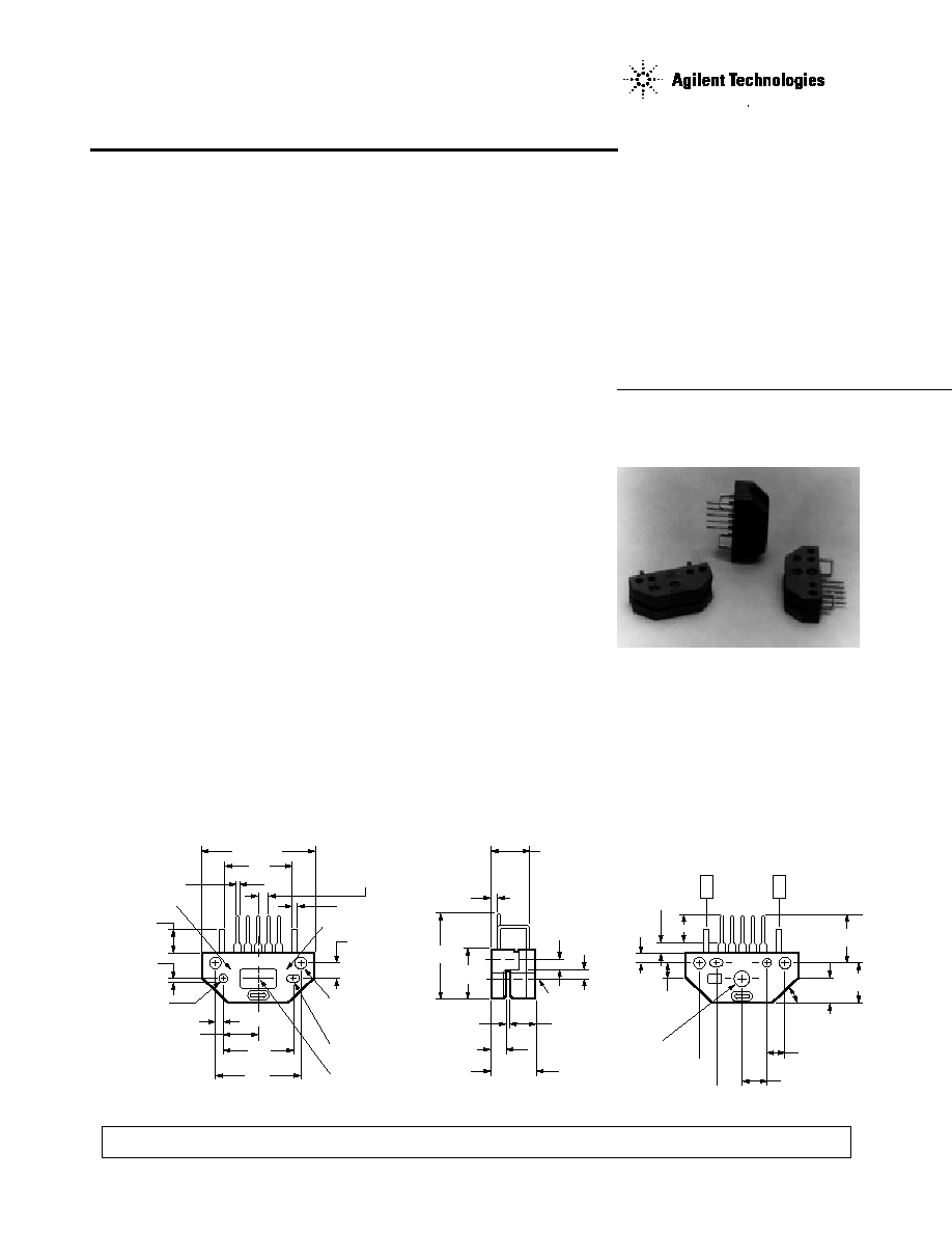
Package Dimensions
Description
The HEDS-9040 and HEDS-9140
series are three channel optical
incremental encoder modules.
When used with a codewheel,
these low cost modules detect
rotary position. Each module
consists of a lensed LED source
and a detector IC enclosed in a
small plastic package. Due to a
highly collimated light source and
a unique photodetector array,
these modules provide the same
high performance found in the
HEDS-9000/9100 two channel
encoder family.
ESD WARNING: NORMAL HANDLING PRECAUTIONS SHOULD BE TAKEN TO AVOID STATIC DISCHARGE.
26.67 (1.05)
HEDS-9040
15.2
(0.60)
CL
17.27
(0.680)
20.96
(0.825)
1.85 (0.073)
8.64 (0.340)
REF.
ALIGNING RECESS
2.44/2.41 DIA.
(0.096/0.095)
2.16 (0.085)
DEEP
1.02 ± 0.10
(0.040 ± 0.004)
5.1 (0.20)
X00
YY WW
OPTION CODE
0.63 (0.025)
SQR. TYP.
2.54 (0.100) TYP.
DATE CODE
1.0 (0.04)
3.73 ± 0.05
(0.147 ± 0.002)
2.67 (0.105) DIA.
MOUNTING THRU
HOLE 2 PLACES
2.44/2.41 X 2.79
(0.096/0.095 X 0.110)
2.16 (0.085) DEEP
OPTICAL CENTER
1.52 (0.060)
20.8
(0.82)
11.7
(0.46)
8.6 (0.34)
1.78 ± 0.10
(0.070 ± 0.004)
2.92 ± 0.10
(0.115 ± 0.004)
10.16
(0.400)
5.46 ± 0.10
(0.215 ± 0.004)
OPTICAL
CENTER LINE
2.54
(0.100)
2.21
(0.087)
5.8
(0.23)
6.35 (0.250) REF.
4.11 (0.162)
OPTICAL
CENTER
45°
8.81
(0.347)
11.9
(0.47)
4.75 ± 0.01
(0.187 ± 0.004)
2.9
(0.11)
1.8
(0.07)
6.9 (0.27)
V
CC
GND
5 CH. B
4 V
CC
3 CH. A
2 CH. 1
1 GND
SIDE A
SIDE B
TYPICAL DIMENSIONS IN
MILLIMETERS AND (INCHES)
2
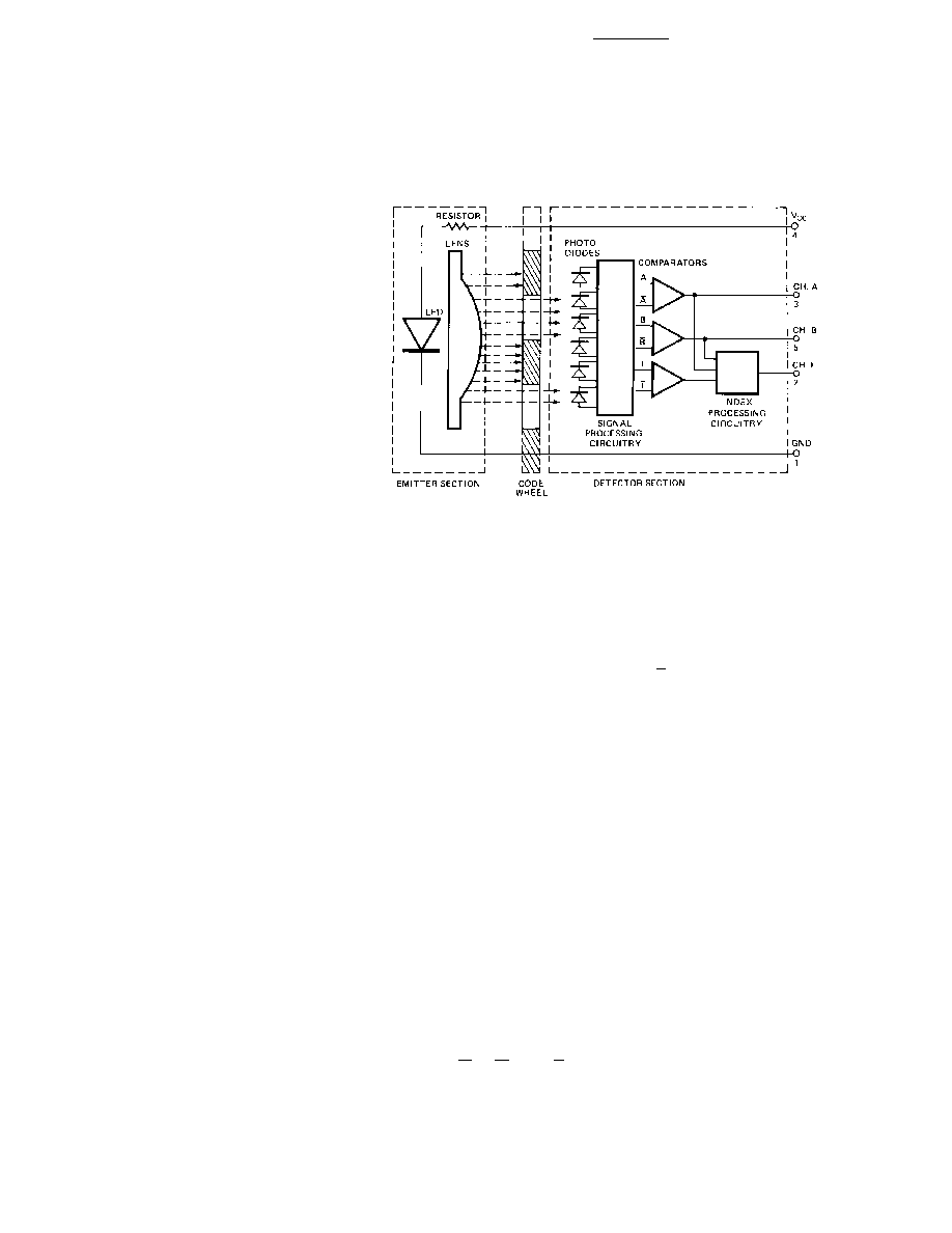
wheel. These detectors are also
spaced such that a light period on
one pair of detectors corresponds
to a dark period on the adjacent
pair of detectors. The photodiode
outputs are then fed through the
signal processing circuitry
resulting in A, A, B, B, I and I.
Comparators receive these signals
and produce the final outputs for
channels A and B. Due to this
integrated phasing technique, the
digital output of channel A is in
quadrature with that of channel B
(90 degrees out of phase).
The output of the comparator for
I and I is sent to the index
processing circuitry along with
the outputs of channels A and B.
The final output of channel I is an
index pulse P
O
which is generated
once for each full rotation of the
codewheel. This output P
O
is a
one state width (nominally 90
electrical degrees), high true
index pulse which is coincident
with the low states of channels A
and B.
Block Diagram
Theory of Operation
The HEDS-9040 and 9140 are
emitter/detector modules.
Coupled with a codewheel, these
modules translate the rotary
motion of a shaft into a three-
channel digital output.
As seen in the block diagram, the
modules contain a single Light
Emitting Diode (LED) as its light
source. The light is collimated
into a parallel beam by means of a
single polycarbonate lens located
directly over the LED. Opposite
the emitter is the integrated
detector circuit. This IC consists
of multiple sets of photodetectors
and the signal processing
circuitry necessary to produce the
digital waveforms.
The codewheel rotates between
the emitter and detector, causing
the light beam to be interrupted
by the pattern of spaces and bars
on the codewheel. The photo-
diodes which detect these
interruptions are arranged in a
pattern that corresponds to the
radius and design of the code-
The HEDS-9040 and 9140 have
two channel quadrature outputs
plus a third channel index output.
This index output is a 90
electrical degree high true index
pulse which is generated once for
each full rotation of the
codewheel.
The HEDS-9040 is designed for
use with a HEDX-614X codewheel
which has an optical radius of
23.36 mm (0.920 inch). The
HEDS-9140 is designed for use
with a HEDS-5140 codewheel
which has an optical radius of
11.00 mm (0.433 inch).
The quadrature signals and the
index pulse are accessed through
five 0.025 inch square pins
located on 0.1 inch centers.
Standard resolutions between 256
and 2000 counts per revolution
are available. Consult local
Agilent sales representatives for
other resolutions.
Applications
The HEDS-9040 and 9140
provide sophisticated motion
control detection at a low cost,
making them ideal for high
volume applications. Typical
applications include printers,
plotters, tape drives, and
industrial and factory automation
equipment.
Note: Agilent Technologies
encoders are not recommended
for use in safety critical
applications. Eg. ABS braking
systems, power steering, life
support systems and critical
care medical equipment. Please
contact sales representative if
more clarification is needed.
3
State Width Error (
S):
The
deviation, in electrical degrees, of
each state width from its ideal
value of 90
°
e.
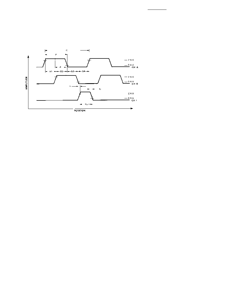
Phase (
):
The number of
electrical degrees between the
center of the high state of channel
A and the center of the high state
of channel B. This value is
nominally 90
°
e for quadrature
output.
Phase Error (
):
The deviation
of the phase from its ideal value
of 90
°
e.
Direction of Rotation:
When the
codewheel rotates in the direction
of the arrow on top of the
module, channel A will lead
channel B. If the codewheel
rotates in the opposite direction,
channel B will lead channel A.
Optical Radius (R
OP
):
The
distance from the codewheel's
center of rotation to the optical
center (O.C.) of the encoder
module.
Index Pulse Width (P
O
):
The
number of electrical degrees that
an index is high during one full
shaft rotation. This value is
nominally 90
°
e or 1/4 cycle.
Output Waveforms
angle which gives rise to one
electrical cycle, and the nominal
angular increment of 1/N of a
revolution.
Pulse Width (P):
The number of
electrical degrees that an output
is high during 1 cycle. This value
is nominally 180
°
e or 1/2 cycle.
Pulse Width Error (
P):
The
deviation, in electrical degrees, of
the pulse width from its ideal
value of 180
°
e.
State Width (S):
The number of
electrical degrees between a
transition in the output of channel
A and the neighboring transition
in the output of channel B. There
are 4 states per cycle, each
nominally 90
°
e.
Definitions
Count (N):
The number of bar
and window pairs or counts per
revolution (CPR) of the
codewheel.
One Cycle (C):
360 electrical
degrees (
°
e), 1 bar and window
pair.
One Shaft Rotation:
360
mechanical degrees, N cycles.
Position Error (
):
The
normalized angular difference
between the actual shaft position
and the position indicated by the
encoder cycle count.
Cycle Error (
C):
An indication
of cycle uniformity. The differ-
ence between an observed shaft
Note:
1. Absolute maximums for HEDS-5140/6140 codewheels only.
Absolute Maximum Ratings
Storage Temperature, T
S .............................................................
- 40
°
C to +100
°
C
Operating Temperature, T
A ........................................................
- 40
°
C to +100
°
C
Supply Voltage, V
CC ...............................................................................
-0.5 V to 7 V
Output Voltage, V
O .................................................................................
- 0.5 V to V
CC
Output Current per Channel, I
OUT ............................................
-1.0 mA to 5 mA
Shaft Axial Play ................................................
±
0.25 mm (
±
0.010 in.)
Shaft Eccentricity Plus Radial Play ..................... 0.1 mm (0.004 in.) TIR
Velocity ........................................................................... 30,000 RPM
[1]
Acceleration ............................................................. 250,000 rad/sec
2[1]
4
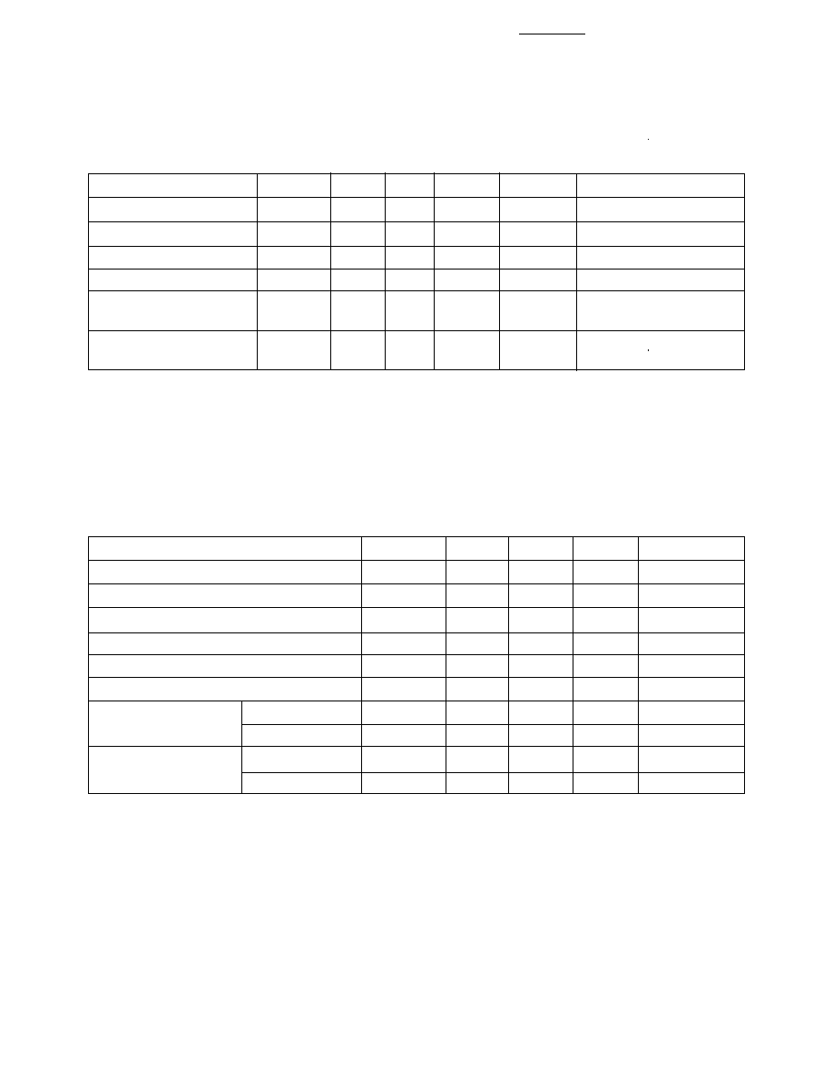
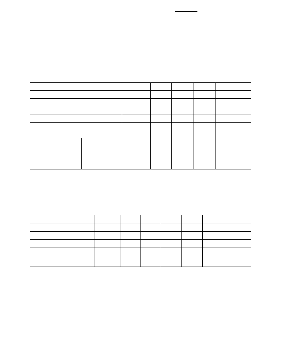
Recommended Operating Conditions
Encoding Characteristics
HEDS-9040 (except #T00), HEDS-9140
Encoding Characteristics over Recommended Operating Range and Recommended Mounting Tolerances
unless otherwise specified. Values are for the worst error over the full rotation of HEDS-5140 and HEDS-
6140 codewheels.
CH. B or CH. A fall
CH. A or CH. B rise
Parameter
Symbol
Min.
Typ.
[1]
Max.
Units
Cycle Error
C
3
5.5
°
e
Pulse Width Error
P
7
30
°
e
Logic State Width Error
S
5
30
°
e
Phase Error
2
15
°
e
Position Error
10
40
min. of arc
Index Pulse Width
P
O
60
90
120
°
e
CH. I rise after
-25
°
C to +100
°
C
t
1
10
100
250
ns
-40
°
C to +100
°
C
t
1
-300
100
250
ns
CH. I fall after
-25
°
C to +100
°
C
t
2
70
150
300
ns
-40
°
C to +100
°
C
t
2
70
150
1000
ns
Note:
1. Module mounted on tolerance circle of
±
0.13 mm (
±
0.005 in.) radius referenced from module Side A aligning recess centers. 2.7 k
pull-up resistors used on all encoder module outputs.
Parameter
Symbol
Min.
Typ.
Max.
Units
Notes
Temperature
T
A
- 40
100
°
C
Supply Voltage
V
CC
4.5
5.0
5.5
Volts
Ripple < 100 mV
p-p
Load Capacitance
C
L
100
pF
2.7 k
pull-up
Count Frequency
f
100
kHz
Velocity (rpm) x N/60
Shaft Perpendicularity
±
0.25
mm
6.9 mm (0.27 in.) from
Plus Axial Play
(
±
0.010)
(in.)
mounting surface
Shaft Eccentricity Plus
0.04
mm (in.)
6.9 mm (0.27 in.) from
Radial Play
(0.0015)
TIR
mounting surface
Note: The module performance is guaranteed to 100 kHz but can operate at higher frequencies. For the HEDS-9040 #T00 for operation
below 0
°
C and greater than 50 kHz the maximum Pulse Width and Logic State Width errors are 60
°
e.
5
Encoding Characteristics
HEDS-9040 #T00
Encoding Characteristics over Recommended Operating Range and Recommended Mounting Tolerances
unless otherwise specified. Values are for the worst error over the full rotation of HEDM-614X Option TXX
codewheel.
Parameter
Symbol
Min.
Typ.
[1]
Max.
Units
Cycle Error
C
3
7.5
°
e
Pulse Width Error
P
7
50
°
e
Logic State Width Error
S
5
50
°
e
Phase Error
2
15
°
e
Position Error
2
20
min. of arc
Index Pulse Width
P
O
40
90
140
°
e
CH. I rise after
-40
°
C to +100
°
C
t
1
10
450
1500
ns
CH. I fall after
-40
°
C to +100
°
C
t
2
10
250
1500
ns
Note:
1. Module mounted on tolerance circle of
±
0.13 mm (
±
0.005 in.) radius referenced from module Side A aligning recess centers. 2.7 k
pull-up resistors used on all encoder module outputs.
CH. B or CH. A fall
CH. A or CH. B rise
Electrical Characteristics
Electrical Characteristics over Recommended Operating Range.
Notes:
1. Typical values specified at V
CC
= 5.0 V and 25
°
C.
2. t
r
and t
f
80 nsec for HEDS-9040 #T00.
Parameter
Symbol
Min.
Typ.
[1]
Max.
Units
Notes
Supply Current
I
CC
30
57
85
mA
High Level Output Voltage
V
OH
2.4
V
I
OH
= -200
µ
A max.
Low Level Output Voltage
V
OL
0.4
V
I
OL
= 3.86 mA
Rise Time
t
r
180
[2]
ns
C
L
= 25 pF
R
L
= 2.7 k
pull-up
Fall Time
t
f
49
[2]
ns