
REV. B
Information furnished by Analog Devices is believed to be accurate and
reliable. However, no responsibility is assumed by Analog Devices for its
use, nor for any infringements of patents or other rights of third parties that
may result from its use. No license is granted by implication or otherwise
under any patent or patent rights of Analog Devices.
a
ADC912A
One Technology Way, P.O. Box 9106, Norwood, MA 02062-9106, U.S.A.
Tel: 781/329-4700
www.analog.com
Fax: 781/326-8703
© Analog Devices, Inc., 2001
CMOS Microprocessor-Compatible
12-Bit A/D Converter
FUNCTIONAL BLOCK DIAGRAM
THREE-STATE
OUTPUT
DRIVERS
THREE-STATE
OUTPUT
DRIVERS
CLOCK
OSCILLATOR
CONTROL
LOGIC
MULTIPLEXER
12-BIT LATCH
12-BIT DAC
SUCCESSIVE
APPROXIMATION
REGISTER
ADC912A
AGND V
REFIN
A
IN
V
DD
V
SS
CLK OUT
CLK IN
HBEN
CS
RD
BUSY
D
11
D
7
D
8
D
4
DGND D
3/11
D
0/8
5k
4
8
8
ANALOG INPUT
DIGITAL OUTPUT
100
90
10
0%
TRANSITION NOISE
Figure 2. Transition Noise Cross Plot
FEATURES
Low Cost
Low Transition Noise between Code
12-Bit Accurate
1/2 LSB Nonlinearity Error over Temperature
No Missing Codes at All Temperatures
10 s Conversion Time
Internal or External Clock
8- or 16-Bit Data Bus Compatible
Improved ESD Resistant Design
Latchup Resistant Epi-CMOS Processing
Low 95 mW Power Consumption
Space-Saving 24-Lead 0.3" DIP, or 24-Lead SOIC
APPLICATIONS
Data Acquisition Systems
DSP System Front End
Process Control Systems
Portable Instrumentation
GENERAL DESCRIPTION
The ADC912A is a monolithic 12-bit accurate CMOS A/D
converter. It contains a complete successive-approximation A/D
converter built with a high-accuracy D/A converter, a precision
bipolar transistor high-speed comparator, and successive-
approximation logic including three-state bus interface for logic
compatibility. The accuracy of the ADC912A results from the
addition of precision bipolar transistors to Analog Devices'
advanced-oxide isolated silicon-gate CMOS process. Particular
attention was paid to the reduction of transition noise between
adjacent codes achieving a 1/6 LSB uncertainty. The low noise
design produces the same digital output for dc analog inputs
not located at a transition voltage, see Figures 1 and 2. NPN
digital output transistors provide excellent bus interface timing,
125 ns access and bus disconnect time which results in faster
data transfer without the need for wait states. An external
1.25 MHz clock provides a 10
µs conversion time.
In stand-alone applications an internal clock can be used with
external crystal.
An external negative five-volt reference sets the 0 V to 10 V
input range. Plus 5 V and minus 12 V power supplies result in
95 mW of total power consumption.
256
0
64
128
192
2045
2049
2048
2047
2046
256 SUCCESSIVE
CONVERSIONS
WITH
A
IN
= 4.99756V
OUTPUT CODE Decimal
NUMBER OF OCCURRENCES
Figure 1. Code Repetition

REV. B
2
ADC912ASPECIFICATIONS
(V
DD
= +5 V 5%, V
SS
= 11.4 V to 15.75 V, V
REFIN
= 5 V, Analog Input O V to
10 V; External f
CLK
= 1.25 MHz; 40 C to +85 C applies to ADC912A/F unless otherwise noted.)
Parameter
Symbol
Conditions
Min
Typ
Max
Unit
STATIC ACCURACY
Integral Nonlinearity
INL
1
+1
LSB
Differential Nonlinearity
DNL
1
+1
LSB
Offset Error
V
ZSE
V
DD
= +5 V, V
SS
= 12 V
5
+5
LSB
Gain Error
G
FSE
V
DD
= +5 V, V
SS
= 12 V
6
+6
LSB
Full-Scale Tempco
1
TCG
FS
5
15
ppm/
°C
ANALOG INPUT
Input Voltage Range
V
IN
0
10
V
Input Current Range
I
IN
0
3
mA
POWER SUPPLIES
Positive Supply Current
I
DD
V
DD
= +5 V
2
5
7
mA
Negative Supply Current
I
SS
V
SS
= 12 V
2
3
5
mA
Power Consumption
P
DISS
V
DD
= +5 V
2
, V
SS
= 12 V
2
70
95
mW
Power Supply Rejection Ratio
PSRR+
V
DD
=
±5%, A
IN
= 10 V
1/2
4
LSB
PSRR
V
SS
=
±5%, A
IN
= 10 V
1/2
4
LSB
DIGITAL INPUTS
Logic Input High Voltage
V
INH
CS, RD, HBEN
2.4
V
Logic Input Low Voltage
V
INL
CS, RD, HBEN
0.8
V
Logic Input Current
I
IN
CS, RD, HBEN
±1
µA
Digital Input Capacitance
C
IN
Digital Inputs,
CS, RD, HBEN, CLKIN
7
10
pF
DIGITAL OUTPUTS
Logic Input High Voltage
V
OH
I
SOURCE
= 0.2 mA
4
V
Logic Input Low Voltage
V
OL
I
SINK
= 1.6 mA
0.4
V
Three-State Output Leakage
I
OZ
D
11
D
0/8
10
µA
Digital Input Capacitance
C
OUT
D
11
D
0/8
1
8
15
pF
DYNAMIC PERFORMANCE
Conversion Time
TC
f
CLK
= 1.25 MHz
3
Synchronous Clock
10.4
µs
Asynchronous Clock
10.4
11.2
µs
NOTES
1
Guaranteed by design.
2
Converter inactive;
CS, RD = High, A
IN
= 10 V.
3
See Synchronizing Start Conversion information in Converter Operation Details. Typicals (typ) are median values measured at 25
°C. See Typical Performance
Characteristics for additional information.
Specifications subject to change without notice.
3k
C
L
DGND
DBN
A. HIGH-Z TO V
OH
(
t
3
)
AND V
OL
TO V
OH
(
t
6
)
C
L
3k
DGND
DBN
5V
B. HIGH-Z TO V
OL
(
t
3
)
AND V
OH
TO V
OL
(
t
6
)
Figure 3. Load Circuits for Access Time
3k
10pF
DGND
DBN
A. V
OH
TO HIGH-Z
10pF
3k
DGND
DBN
5V
B. V
OL
TO HIGH-Z
Figure 4. Load Circuits for Output Float Delay

REV. B
ADC912A
3
t
CONV
t
6
t
7
DATA
OUTPUTS
READ
D
11
D
10
D
9
D
8
D
7
D
6
D
5
D
4
D
3/11
D
2/10
D
1/9
D
0/8
DB
11
DB
10
DB
9
DB
8
DB
7
DB
6
DB
5
DB
4
DB
3
DB
2
DB
1
DB
0
t
1
t
2
t
3
t
5
t
1
t
10
OLD DATA
DB
11
DB
0
NEW DATA
DB
11
DB
0
CS
RD
BUSY
DATA
Figure 5. Parallel Read Timing Diagram, Slow-Memory
Mode (HBEN = LOW)
CS
RD
BUSY
DATA
HBEN
DATA
OUTPUTS
FIRST READ
SECOND READ
D
7
D
6
D
5
D
4
D
3/11
D
2/10
D
1/9
D
0/8
DB
7
DB
6
DB
5
DB
4
DB
3
DB
2
DB
1
DB
0
LOW
LOW
LOW
LOW
DB
11
DB
10
DB
9
DB
8
t
8
t
1
t
2
t
3
t
CONV
t
6
t
7
t
5
t
9
t
8
t
1
t
10
t
3
t
7
t
5
t
9
t
4
NEW DATA
DB
7
DB
0
NEW DATA
DB
11
DB
8
OLD DATA
DB
7
DB
0
Figure 6. Two-Byte Read Timing Diagram, Slow-Memory
Mode
TIMING CHARACTERISTICS
1, 2
(V
DD
= +5 V 5%, V
SS
= 11.4 V to 15.75 V, V
REFIN
= 5 V, Analog Input 0 V to 10 V;
External f
CLK
= 1.25 MHz; 40 C to +85 C applies to ADC912A/F unless otherwise noted. See Figures 5 to 8.)
Parameter
Symbol
Conditions
Min
Typ
Max
Unit
CS to RD Setup Time
t
1
0
ns
RD to BUSY Propagation Delay
t
2
150
ns
Data Access Time after READ
t
3
3
C
L
= 100 pF
65
125
ns
Read Pulsewidth
t
4
3
90
ns
CS to RD Hold Time
t
5
0
ns
New Data Valid after
BUSY
t
6
3
C
L
= 100 pF
30
0
ns
Bus Disconnect Time
t
7
20
60
90
ns
HBEN to
RD Setup Time
t
8
20
ns
HBEN to
RD Hold Time
t
9
20
ns
Delay between Successive Read Operations
t
10
350
250
ns
NOTES
1
Guaranteed by design.
2
All input control signals are specified with t
R
= t
F
= 5 ns (10% to 90% of 5 V) and timed from a voltage level of 1.6 V.
3
t
3
, t
4
, and t
6
are measured with the load circuits of Figure 3 and timed for and output to cross 0.8 V or 2.4 V.
4
t
7
is the time required for the data lines to change 0.5 V when loaded with the circuits of Figure 4.
Specifications subject to change without notice.
TIMING DIAGRAMS
CS
RD
BUSY
DATA
t
1
t
2
t
3
t
7
t
3
t
7
t
CONV
t
5
t
1
t
2
t
CONV
t
5
t
4
NEW DATA
DB
11
DB
0
OLD DATA
DB
11
DB
0
DATA
OUTPUTS
D
11
D
10
D
9
D
8
D
7
D
6
D
5
D
4
D
3/11
D
2/10
D
1/9
D
0/8
DB
11
DB
10
DB
9
DB
8
DB
7
DB
6
DB
5
DB
4
DB
3
DB
2
DB
1
DB
0
FIRST READ
(OLD DATA)
SECOND
READ
DB
11
DB
10
DB
9
DB
8
DB
7
DB
6
DB
5
DB
4
DB
3
DB
2
DB
1
DB
0
t
4
Figure 7. Parallel Read Timing Diagram, ROM Mode
(HBEN = LOW)
DATA
OUTPUTS
D
7
D
6
D
5
D
4
D
3/11
D
2/10
D
1/9
D
0/8
FIRST READ
(OLD DATA)
DB
7
DB
6
DB
5
DB
4
DB
3
DB
2
DB
1
DB
0
SECOND READ
LOW
LOW
LOW
LOW
DB
11
DB
10
DB
9
DB
8
THIRD READ
DB
7
DB
6
DB
5
DB
4
DB
3
DB
2
DB
1
DB
0
t
8
t
1
t
2
t
3
t
7
t
4
t
9
t
5
t
8
t
1
t
3
t
4
t
9
t
10
t
3
t
7
t
2
t
4
t
1
t
5
t
8
t
9
t
7
t
5
CS
RD
BUSY
DATA
HBEN
NEW DATA
DB
7
DB
0
NEW DATA
DB
11
DB
8
OLD DATA
DB
7
DB
0
t
CONV
Figure 8. Two-Byte Read Timing Diagram, ROM Mode

REV. B
ADC912A
4
CAUTION
ESD (electrostatic discharge) sensitive device. Electrostatic charges as high as 4000 V readily
accumulate on the human body and test equipment and can discharge without detection. Although
the ADC912A features proprietary ESD protection circuitry, permanent damage may occur on
devices subjected to high-energy electrostatic discharges. Therefore, proper ESD precautions are
recommended to avoid performance degradation or loss of functionality.
WARNING!
ESD SENSITIVE DEVICE
ABSOLUTE MAXIMUM RATINGS
(T
A
= 25
°C, unless otherwise noted)
V
DD
to DGND . . . . . . . . . . . . . . . . . . . . . . . . . 0.3 V to +7 V
V
SS
to DGND . . . . . . . . . . . . . . . . . . . . . . . . . +0.3 V to 7 V
V
REFIN
to DGND . . . . . . . . . . . . . . . . . . . . . . . . . . V
SS
to V
DD
AGND to DGND . . . . . . . . . . . . . . . . 0.3 V to V
DD
+ 0.3 V
A
IN
to AGND . . . . . . . . . . . . . . . . . . . . . . . . 15 V to +15 V
Digital Input Voltage to DGND,
Pins 17, 1921 . . . . . . . . . . . . . . . . . 0.3 V to V
DD
+ 0.3 V
Digital Output Voltage to DGND,
Pins 411, 1316, 18, 22 . . . . . . . . . 0.3 V to V
DD
+ 0.3 V
Table I. Analog Input to Digital Output Code Conversion
Analog Input Voltage
Output Code
*
0 V to 10 V
10 V to +10 V
DB
11
(MSB) DB
0
(LSB)
+FS 1 LSB
9.9976
9.99951
1 1 1 1
1 1 1 1
1 1 1 1
+FS 1 1/2 LSB
9.9964
9.9927
1 1 1 1
1 1 1 1
1111
Midscale + 1/2 LSB
5.0012
0.0024
1 0 0 0
0 0 0 0
0 0 0
Midscale
5.0000
0.0000
1 0 0 0
0 0 0 0
0 0 0 0
FS + 1/2 LSB
0.0012
9.9976
0 0 0 0
0 0 0 0
0 0 0
FS
0.0000
10.000
0 0 0 0
0 0 0 0
0 0 0 0
*The symbol"
" indicates a 0 or 1 with equal probability.
Operating Temperature Range
Extended Industrial: ADC912A/F . . . . . . . 40
°C to +85°C
Storage Temperature . . . . . . . . . . . . . . . . . . 65
°C to +150°C
Lead Temperature (Soldering, 10 sec) . . . . . . . . . . . . . 300
°C
Maximum Junction Temperature (T
J
max) . . . . . . . . . . 150
°C
Package Power Dissipation . . . . . . . . . . . . . . (T
J
maxT
A
)/
JA
Thermal Resistance
JA
Plastic DIP . . . . . . . . . . . . . . . . . . . . . . . . . . . . . . . 57
°C/W
SOIC-24 . . . . . . . . . . . . . . . . . . . . . . . . . . . . . . . . . . . 70
°C
ORDERING GUIDE
Temperature
INL
Package
Model
Range
(LSB)
Package Description
Option
ADC912AFP
40
°C to +85°C
±1
24-Lead Narrow-Body Plastic
N-24
ADC912AFS
40
°C to +85°C
±1
24-Lead Wide-Body SOIC
R-24

REV. B
ADC912A
5
WAFER TEST LIMITS
ADC912AG
Parameter
Symbol
Conditions
Limit
Unit
Integral Nonlinearity
INL
±1
LSB max
Differential Nonlinearity
DNL
±1
LSB max
Offset Error
V
ZSE
Guaranteed by Design
±8
LSB max
Gain Error
G
FSE
±8
LSB max
Analog Input Resistance
R
AIN
4/6
k
min/max
Logic Input High Voltage
V
INH
CS, RD, HBEN
2.4
V min
Logic Input Low Voltage
V
INL
CS, RD, HBEN
0.8
V max
Logic Input Current
I
IN
CS, RD, HBEN
±1
µA max
Logic Output High Voltage
V
OH
I
SOURCE
= 0.2 mA
4
V min
Logic Output Low Voltage
V
OL
I
SINK
= 1.6 mA
0.4
V max
Positive Supply Current
I
DD
V
DD
= +5 V,
CS = RD = V
DD
, A
IN
= +10 V
7
mA max
Negative Supply Current
I
SS
V
SS
= 12 V,
CS = RD = V
DD
, A
IN
= +10 V
5
mA max
NOTE
Electrical tests are performed at wafer probe to the limits shown. Due to variations in assembly methods and normal yield loss, yield after packaging is not guaranteed
for standard product dice. Consult factory to negotiate specifications based on dice lot qualification through sample lot assembly and testing.
(@ V
DD
= +5 V, V
SS
= 12 V or 15 V, V
REF
= 5 V, A
IN
= 0 V to 10 V, and T
A
= 25 C, unless otherwise noted.)
24
23
22
21
20
19
18
17
16
15
14
13
1
2
3
4
5
6
7
8
9
10
11
12
NC
NC
NC
NC
NC
NC
NC
C1
C2
C1
C2
+
+
C1
C2
C1
C2
+
+
10V
5V
+5V
15V
R
R
R
R
R
R
R
R = 10
C1 = 0.01 F
C2 = 4.7 F
NC = NO CONNECT
POWER SUPPLY SEQUENCE:
+5V, 15V, 5V, +10V
ADC912A
TOP VIEW
(Not to Scale)
Figure 9. Burn-In Circuit

REV. B
ADC912A
6
PIN FUNCTION DESCRIPTIONS
Pin
Mnemonic
Description
l
AIN
Analog Input. 0 V to 10 V.
2
VREFIN
Voltage Reference Input. Requires external 5 V reference.
3
AGND
Analog Ground.
4 . . . 11
D
11
. . . D
4
Three-state data outputs become active when
CS and RD are brought low.
13 . . . 16
D
3/11
. . . D
0/8
Individual pin function is dependent upon High Byte Enable (HBEN) input.
DATA BUS OUTPUT,
CS and RD = LOW
Pin 4
Pin 5
Pin 6
Pin 7
Pin 8
Pin 9
Pin 10 Pin 11 Pin 13 Pin 14 Pin 15 Pin 16
Mnemonic
*
D
11
D
10
D
9
D
8
D
7
D
6
D
5
D
4
D
3/11
D
2/10
D
1/9
D
0/8
HBEN = LOW
DB
11
DB
10
DB
9
DB
8
DB
7
DB
6
DB
5
DB
4
DB
3
DB
2
DB
1
DB
0
HBEN = HIGH
DB
11
DB
10
DB
9
DB
8
Low
Low
Low
Low
DB
11
DB
10
DB
9
DB
8
*D
11
. . . D
0/8
are the ADC data output pins.
DB
11
. . . DB
0
are the 12-bit conversion results. DB
11
is the MSB.
1
2
DGND
Digital Ground.
17
CLK IN
Clock Input Pin. An external TTL-compatible clock may be applied to this pin. Alternatively a crystal or
ceramic resonator may be connected between CLK IN (Pin 17) and CLK OUT (Pin 18).
18
CLK OUT
Clock Output Pin. An inverted CLK IN signal appears at CLK OUT when an external clock is used. See
CLK IN (Pin 17) description for crystal (resonator).
19
HBEN
High Byte Enable Input. Its primary function is to multiplex the 12 bits of conversion data onto the lower
D
7
. . . D
0/8
outputs (4 MSBs or 8 LSBs). See pin description 4 . . . 11 and 13 . . . 16. Also disables
conversion start when HBEN is high.
20
RD
READ Input. This active LOW signal, in conjunction with
CS, is used to enable the output data three
state drivers and initiates a conversion if CS and HBEN are low.
21
CS
Chip Select Input. This active LOW signal, in conjunction with
RD, is used to enable the output data
three-state drivers and initiates a conversion if
RD and HBEN are low.
22
BUSY
BUSY output indicates converter status. BUSY is LOW during conversion.
23
V
SS
Negative Supply, 12 V or 15 V.
24
V
DD
Positive Supply, +5 V.
PIN CONFIGURATION
24
23
22
21
20
19
18
17
16
15
14
13
1
2
3
4
5
6
7
8
9
10
11
12
V
DD
V
SS
D
0/8
D
1/9
D
2/10
D
3/11
HBEN
CLK OUT
CLK IN
BUSY
CS
RD
A
IN
V
REFIN
AGND
D
11
D
10
D
9
D
8
D
7
D
6
D
5
D
4
DGND
ADC912A
TOP VIEW
(Not to Scale)
1
2
3
4
5
6
7
8
9
10
11
12
A
IN
V
REFIN
AGND
D
11
D
10
D
9
D
8
D
7
D
6
D
5
D
4
DGND
C1
+
0V TO 10V
ANALOG INPUT
5V
REFERENCE
SOURCE
ADC912A
8-BIT OR 16-BIT P DATA BUS
XTAL = 1MHz, C1 = 0.1 F, C3 = 10 F
C3, C4
= 30pF TO 100pF DEPENDING ON XTAL CHOSEN
24
23
22
21
20
19
18
17
16
15
14
13
+5V
12V TO 15V
STATUS
OUTPUT
P
CONTROL
INPUTS
XTAL
C3
C4
V
DD
V
SS
D
0/8
D
1/9
D
2/10
D
3/11
HBEN
CLK OUT
CLK IN
BUSY
CS
RD
C2
Figure 10. Basic Connection Diagram
REV. B
7
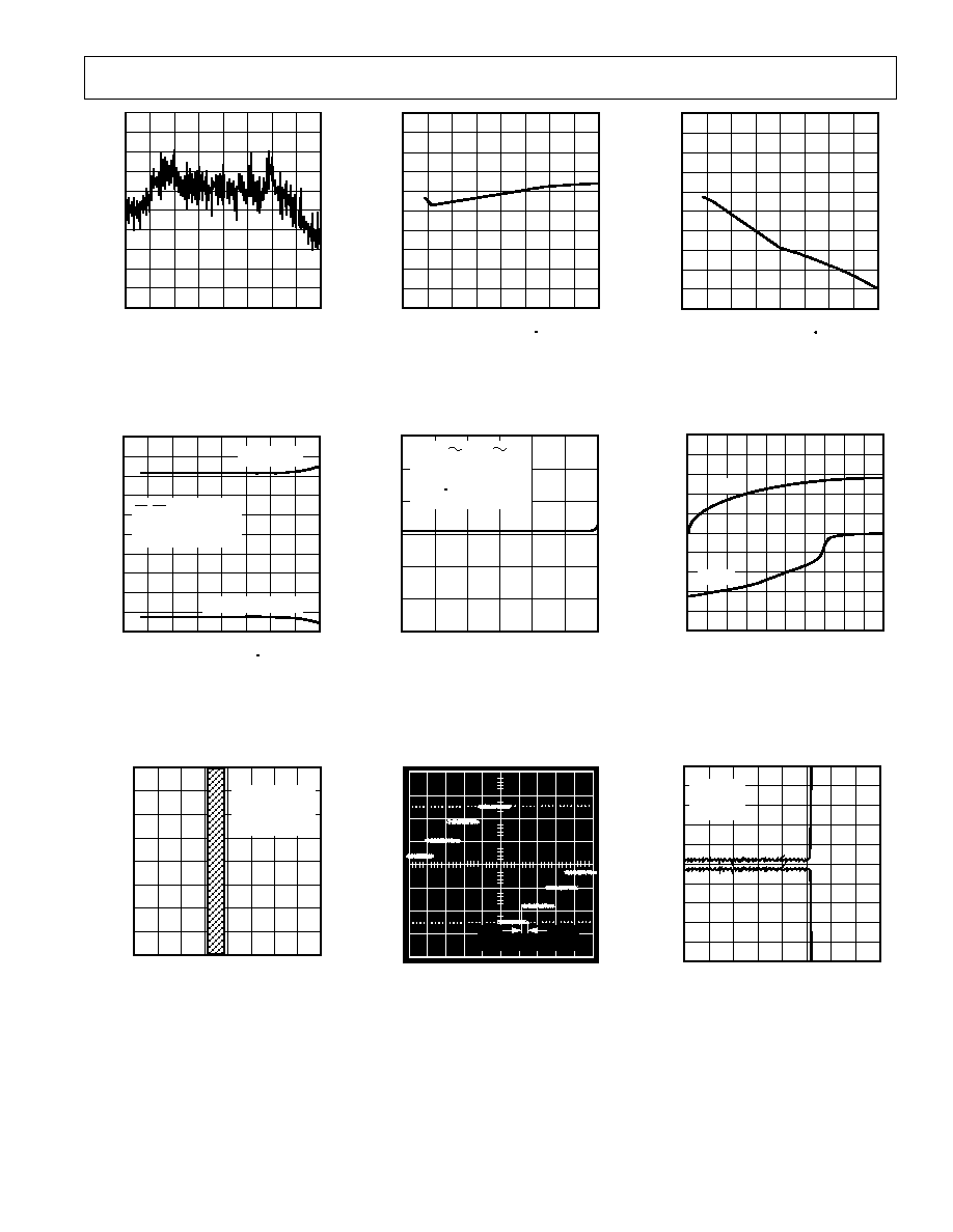
Typical Performance CharacteristicsADC912A
0.4
4096
0.4
0
0
0.2
0.2
2048
1024
3072
DIGITAL OUTPUT CODE
INL
NONLINEARITY ERR
OR
LSB
TPC 1. Nonlinearity Error vs. Digital
Output Code
6
4
125
1
3
50
2
75
2
0
1
3
4
5
100
25
50
25
0
75
TEMPERATURE C
SUPPL
Y CURRENT
mA
CS, RD = LOGIC HIGH
A
IN
= 10V
CLK = 1MHz XTAL
I
SS
@ V
SS
= 15.75V
V
DD
@ 5.25V
TPC 4. Supply Current vs.
Temperature
256
0
64
128
192
2045
2049
2048
2047
2046
256 SUCCESSIVE
CONVERSIONS
WITH
A
IN
= 4.99756V
OUTPUT CODE Decimal
NUMBER OF OCCURRENCES
TPC 7. Code Repetition
5
5
125
2
4
50
3
75
1
1
0
2
3
4
100
25
50
25
0
75
TEMPERATURE C
OFFSET ERR
OR
LSB
TPC 2. Offset Error vs. Temperature
80
0
1M
40
1k
60
100k
10k
CLK IN FREQUENCY Hz
C
OUT
= 20pF
f
CONV
= 1/13 f
CLK IN
T
A
= 25 C
EXT CLK IN
P
DISS
= IDD 5 + ISS 12
P
DISS
mW
TPC 5. Power Dissipation vs. CLK IN
Frequency
ANALOG INPUT
DIGITAL OUTPUT
100
90
10
0%
TRANSITION NOISE
TPC 8. Transition Noise Cross Plot
6
4
125
1
3
50
2
75
2
0
1
3
4
5
100
25
50
25
0
75
TEMPERATURE C
GAIN ERR
OR
LSB
TPC 3. Gain Error vs. Temperature
50
50
20
40
1
30
0
10
10
0
20
30
40
5
4
3
2
V
O
OUTPUT VOLTAGE Volts
DIGIT
AL OUTPUT CURRENT
mA
I
SINK
I
SOURCE
TPC 6. Digital Output Current vs.
Output Voltage
0
2
4
20
0
2
4
10
15
5
CONVERSION TIME s
LINEARITY ERR
OR
LSB
V
DD
= +5V
V
SS
= 12V
T
A
= 25 C
TPC 9. Linearity Error vs. Conversion
Time

REV. B
ADC912A
8
CIRCUIT CHARACTERISTICS
The characteristic curves provide more complete static and
dynamic accuracy information necessary for repetitive sampling
applications often used in DSP processing. One of the impor-
tant characteristic curves provided displays integral nonlinearity
error (INL) versus output code with a typical value of
±1/4 LSB.
Another very important characteristic associated with INL is the
transition noise shown in the transition noise cross plot. The
ADC912A offers extremely small,
±1/6 LSB, transition noise
which maintains the system signal-to-noise ratio in DSP processing
applications. Code repetition plots show the precision internal
comparator of the ADC912A making the same decision every
time for dc input voltages. Code repetition along with no miss-
ing codes assures proper performance when the ADC912A is
used in servo-control systems.
CONVERTER OPERATION DETAILS
The
CS, RD, and HBEN digital inputs control the start of
conversion. A high-to-low on both
CS and RD initiate a conver-
sion sequence. The HBEN high-byte-enable input must be low
or coincident with the read
RD input edge. The start of conver-
sion resets the internal successive approximation register (SAR)
and enables the three-state outputs. See Figure 11. The busy
line is active low during the conversion process.
SAR
12-BIT LATCH
+
5k
2.5k
A
IN
V
REFIN
AGND
0 TO
V
REF
COMPARATOR
12
0V TO 10V
Figure 11. Simplified Analog Input Circuitry of ADC912A
During conversion, the SAR sequences the internal voltage
output DAC from the most significant bit (MSB) to the least
significant bit (LSB). The analog input connects to the
comparator via a 5 k
resistor. The DAC, which has a 2.5 k
output resistance, connects to the same comparator input.
The comparator, performing a zero crossing detection, tests the
addition of successively weighted bits from the DAC output
versus the analog input signal. The MSB decision occurs 200 ns
after the second positive edge of the CLK IN following conver-
sion initiation. The remaining 11-bit trials occur after the next
11 positive CLK IN edges. Once a conversion cycle is started it
cannot be stopped or restarted, without upsetting the remaining
bit decisions. Every conversion cycle must have 13 negative and
positive CLK IN edges. At the end of conversion the compara-
tor input voltage is zero. The SAR contains the 12-bit data
word representing the analog input voltage. The BUSY line
returns to logic high, signaling end of conversion. The SAR
transfers the new data to the 12-bit latch.
SYNCHRONIZING START CONVERSION
Aligning the negative edge of
RD with the rising edge of CLK
IN provides synchronization of the internal start conversion
signal to other system devices for sampling applications.
When the negative edge of
RD is aligned with the positive edge
of CLK IN, the conversion will take 10.4 microseconds. The
minimum setup time between the negative edge of CLK IN and
the negative edge of
RD is 180 ns. Without synchronization the
conversion time will vary from 12.5 to 13.5 clock cycles. See
Figure 12.
CLK IN
CS RD
,
BUSY
180ns MIN
DB
11
DB
10
DB
9
DB
0
(MSB)
BIT DECISION
MADE
Figure 12. External Clock Input Synchronization
POWER ON INITIALIZATION
During system power-up the ADC912A comes up in a random
state. Once the clock is operating or an external clock is applied,
the first valid conversion begins with the application of a high-
to-low transition on both
CS and RD. The next 13 negative
clock edges complete the first conversion, producing valid data
at the digital outputs. This is important in battery-operated
systems where power supplies are shut down between measure-
ment times.
DRIVING THE ANALOG INPUT
During conversion, the internal DAC output current modulates
the analog input current at the CLK IN frequency of 1.25 MHz.
The analog input to the ADC912A must not change during the
conversion process. This requires an external buffer with low
output impedance at 1.25 MHz. Suitable devices meeting this
requirement include the OP27, OP42, and the SMP-11.
CLK
OUT
C2
CLK
IN
ADC912A
INTERNAL
CLOCK
1M
*
*CRYSTAL OR CERAMIC RESONATOR
C1
Figure 13. ADC912A Simplified Internal Clock Circuit

REV. B
ADC912A
9
INTERNAL CLOCK OSCILLATOR
Figure 13 shows the ADC912A internal clock circuit. The clock
oscillates at the external crystal or ceramic resonator frequency.
The 1.25 MHz crystal or ceramic resonator connects between
the CLK IN (Pin 17) and the CLK OUT (Pin 18). Capacitance
values (C1, C2) depend on the crystal or ceramic resonator
manufacturer. The crystal vendors should be qualified due to
variations in C1 and C2 values required from vendor to vendor.
Typical values range from 30 pF to 100 pF.
EXTERNAL CLOCK INPUT
A TTL compatible signal connected to CLK IN provides proper
converter clock operation. No connection is necessary to the
CLK OUT pin. The duty cycle of the external clock input can
vary from 45% to 55%. Figure 12 shows the important waveforms.
EXTERNAL REFERENCE
A low output resistance, negative five volt reference is necessary.
The external reference should be able to supply 3 mA of refer-
ence current. A bypass capacitor is necessary on the reference
input lead to minimize system noise as the internal DAC switches.
The reference input to the internal DAC is code dependent requir-
ing anywhere from zero to 3 mA. The reference voltage tolerance
has a direct influence on A/D converter full-scale voltage, and
the maximum input full-scale voltage equals 2
× V
REF
. The
ADC912A is designed for ratiometric operation, but operation
using reference voltages between 5.00 V and 0 V will result in
degraded linearity performance. Integral linearity is fully tested and
guaranteed for references of 5 V. Figure 14 provides a good
5 V reference that does not require precision resistors.
INPUT
V
OUT
TRIM
GND
REF02
+5V TO +15V
10k
100
100
+
V+
V
10 F//0.01 F
5V
OUTPUT
0.01 F
OP77
2
4
6
5
2
3
12V TO 15V
TRIM IS OPTIONAL, ONLY NECESSARY
FOR ABSOLUTE ACCURACY CIRCUITS
OP77
Figure 14. 5 V Reference
UNIPOLAR ANALOG INPUT OPERATION
Figure 15 shows the ideal input/output characteristic for the 0 V
to 10 V input range of the ADC912A. The designed output
code transitions occur midway between successive integer LSB
values (i.e., 0.5 LSB, 1.5 LSBs, 2.5 LSBs . . . FS 1.5 LSBs).
The output code is natural binary with 1 LSB = FS/4096 =
(10/4096) V = 2.44 mV. The maximum full-scale input voltage
is (10
× 4095/4096) V = 9.9976 V.
4095
FS
1
1
2
0
4094
FS-1
FS-2
2
0.5
FULL-SCALE
TRANSITION
AT FS 1.5 LSB
A
IN
ANALOG INPUT IN LSB
DIGIT
AL OUTPUT CODE
Decimal Equiv
alent
Figure 15. Ideal ADC912A Input/Output Transfer
Characteristic
OFFSET AND FULL-SCALE ERROR ADJUSTMENT,
UNIPOLAR OPERATION
For applications where absolute accuracy is important, offset
and full-scale errors can be adjusted to zero. Figure 16 shows
the extra components required for full-scale error adjustment.
Zero offset is achieved by adjusting the null offset of the op amp
driving A
IN
.
10k
20k
200
10
A
IN
AGND
ADC912A*
ZERO
ADJUST
FULL
SCALE
ADJUST
A1
V
IN
0V TO 10V
3
2
4
1
5
6
7
1
3
+12V
A1: OP27 LOWEST NOISE (TRIMMER CONNECTS
BETWEEN PINS 1 & 8, WIPER TO 12V)
OP42 BEST BANDWIDTH
*EXTRA PINS OMITTED FOR CLARITY
12V
Figure 16. Unipolar 0 V to 10 V Operation
Adjust the zero scale first by applying 1.22 mV (equivalent to
0.5 LSB input) to V
IN
. Adjust the op amp offset control until
the digital output toggles between 0000 0000 0000 and 0000
0000 0001. The next step is adjustment of full scale. Apply
9.9963 V (equivalent to FS 1.5 LSB) to V
IN
and adjust R1
until the digital output toggles between 1111 1111 1110 and
1111 1111 1111.

REV. B
ADC912A
10
BIPOLAR ANALOG INPUT OPERATION
Bipolar analog input operation is achieved with an external
amplifier providing an analog offset. Figures 17 and 18 show
two circuit topologies that result in different digital-output cod-
ing. In Figure 17, offset binary coding is produced when the
external amplifier is connected in the inverting mode. Figure 19
shows the ideal transfer characteristics for both the inverting
and noninverting configurations given in Figures 17 and 18.
AGND
V
REFIN
A
IN
0.1 F 10 F
1
2
5V
R2
R1
R3
R4
R
FS
R
Z
V
IN
3
R1 = R2 = 20k
SEE TABLE II FOR VALUES OF R3, R4, R
Z
, AND R
FS
A1: OP27 LOWEST NOISE, OP42 BEST BANDWIDTH
*EXTRA PINS OMITTED FOR CLARITY
ADC912A*
A1
Figure 17. Noninverting Bipolar Analog Input Operation
The scaling resistors chosen in bipolar input applications should
be from the same manufacturer to obtain good resistor tracking
performance over temperature. When potentiometers are used
for absolute adjustment, 0.1% tolerance resistors should still be
used as shown in Figures 17 and 18 to minimize temperature
coefficient errors.
5V
0.1 F 10 F
2
3 AGND
V
REFIN
A
IN
V
IN
1
R1
R2
R3
R
FS
R
Z
SEE TABLE III FOR VALUES OF R1, R2, R3, R4, R
Z
, AND R
FS
A1: OP27 LOWEST NOISE, OP42 BEST BANDWIDTH
*EXTRA PINS OMITTED FOR CLARITY
ADC912A*
+
A1
Figure 18. Inverting Bipolar Analog Input
Calibration of the bipolar analog input circuits (Figures 17 and
18) should begin with zero adjustment first. Apply a +1/2 LSB
analog input to A
IN
, (see Tables II and III) and adjust R
Z
until the
successive digital output codes flicker between the following codes:
For noninverting, Figure 17
1000 0000 0000
1000 0000 0001
For inverting, Figure 18
0111 1111 1111
0111 1111 1110
Next, adjust full scale by applying a FS3/2 LSB analog input to
A
IN
, (see Tables II and III) and adjust R
FS
until the successive
digital output codes flicker between the following codes:
For Noninverting, Figure 17
1111 1111 1110
1111 1111 1111
For Inverting, Figure 18
0000 0000 0001
0000 0000 0000
Table II. Resistor and Potentiometer Values Required for
Figure 17
V
IN
Range
R3
R4
R
Z
R
FS
1/2 LSB
FS/23/2 LSB
V
k
k
k
k
mV
V
±2.5
0
40.2
0.5
0.5
0.61
2.49817
±5.0
20.0
19.8
0.5
1.0
1.22
4.99634
±10.0
29.8
10.0
0.5
0.5
2.44
9.99268
Table III. Resistor and Potentiometer Values Required for
Figure 18
V
IN
Range
R1
R2
R3
R
Z
R
FS
1/2 LSB
FS/23/2 LSB
V
k
k
k
k
k
mV
V
±2.5
20.0 41.2 40.2 2
1
0.61
2.49817
±5.0
20.0 20.5 20.0 1
1
1.22
4.99634
±10.0
20.0 10.5 10.2 0.5
1
2.44
9.99268
111...110
100...000
111...111
100...001
011...111
011...110
000...001
000...000
DIGITAL OUTPUT
0V
FS
2
FS
2
+
INVERTING
FIGURE 18
V
IN
Input Voltage
FS
2
+
1LSB
NON-
INVERTING
FIGURE 17
Figure 19. Ideal Input/Output Transfer Characteristics for
Bipolar Input Circuits

REV. B
ADC912A
11
MICROPROCESSOR INTERFACING
The ADC912A has self-contained logic for both 8-bit and 16-bit
data bus interfacing. The output data can be formatted into
either a 12-bit parallel word for a 16-bit data bus or an 8-bit
data word pair for an 8-bit data bus. Data is always right justi-
fied, i.e., LSB is the most right-hand bit in a 16-bit word. For a
two-byte read, only data outputs D
7
. . . D
0/8
are used. Byte
selection is governed by the HBEN input which controls an
internal digital multiplexer. This multiplexes the 12 bits of
conversion data onto the lower D
7
. . . D
0/8
outputs (4 MSBs or
8 LSBs) where it can be read in two read cycles. The 4 MSBs
always appear on D
11
. . . D
8
whenever the three-state output
drivers are turned on. See Figure 20.
Two A/D conversion modes of operation are available for both
data bus sizes: the ROM mode and the Slow-Memory mode.
D
Q
"1"
ACTIVE HIGH
(HBEN = "0")
CONVERSION START
(POSITIVE EDGE
TRIGGER)
ACTIVE HIGH
(HBEN = "1")
ENABLE THREE-STATE
OUTPUTS
PINS: D
11
... D
0/8
DATA BITS: DB
11
... DB
0
PINS: D
7
... D
4
DATA BITS: LOGIC LOW
PINS: D
3/11
... D
0/8
DATA BITS: DB
11
... DB
8
ENABLE THREE-STATE
OUTPUTS
PINS: D
11
... D
8
DATA BITS: DB
11
... DB
8
HBEN
ADC912A
CS
RD
BUSY
CLR
Figure 20. Internal Logic for Control Inputs
CS, RD, and
HBEN
In the ROM mode each READ instruction obtains new, valid
data, assuming the minimum timing requirements are satisfied.
However, since the data output from a current READ instruc-
tion was generated from a conversion initiated by a previous
READ operation, the current data may be out-of-date. To be
sure of obtaining up-to-date data, READ instructions may be
coded in pairs (with some NOPs between them); use only the
data from the second READ in each pair. The first READ starts
the conversion, the second READ gets the results.
The Slow-Memory mode is the simplest. It is the method of
choice where compact coding is essential, or where software
bugs are a hazard. In this mode, a single READ instruction will
initiate a data conversion, interrupt the microprocessor until
completion (WAIT states are introduced), then read the results.
If the system throughput tolerates WAIT states, and the hardware
is correct, then the Slow-Memory mode is virtually immune to
subsequent software modifications. Placing the microprocessor
in the WAIT state has an additional advantage of quieting the
digital system to reduce noise pickup in the analog conversion
circuitry. The 12-bit parallel Slow-Memory mode provides the
fastest analog sampling rate combined with digital data transfer
rate for sampled-data systems.
PARALLEL READ, SLOW-MEMORY MODE
(HBEN = LOW)
Figure 5 shows the timing diagram and data bus status for Par-
allel Read, Slow-Memory Mode.
CS and RD going low triggers
a conversion and the ADC912A acknowledges by taking
BUSY
low. Data from the previous conversion appears on the three-
state data outputs.
BUSY returns high at the end of conversion,
when the output latches have been updated, and the conversion
result is placed on data outputs D
11
. . . D
0/8
.
TWO-BYTE READ, SLOW-MEMORY MODE
For a two-byte read only the eight data outputs D
7
. . . D
0/8
are used. Conversion start procedure and data output status for
the first read operation is identical to Parallel Read, Slow-Memory
Mode. See Figure 6, Timing Diagram and Data Bus Status. At
the end of conversion, the low data byte (DB
7
. . . DB
0
) is read
from the A/D converter. A second READ operation with HBEN
high places the high byte on data outputs D
3/11
. . . D
0/8
and
disables conversion start. Note the 4 MSBs also appear on data
outputs D
11
. . . D
8
during these two READ operations.
PARALLEL READ, ROM MODE (HBEN = LOW)
A conversion is started with a READ operation. The 12 bits of
data from the previous conversion are available on data outputs
D
11
. . . D
0/8
(see Figure 7). This data may be disregarded if
not required. A second READ operation reads the new data
(DB
11
. . . DB
0
) and starts another conversion. A delay at least
as long as the ADC912A conversion time must be allowed be-
tween READ operations. If a READ takes place prior to the end
of 13 CLKS of the ADC conversion, the remaining bits not yet
tested will be invalid.
TWO-BYTE READ, ROM MODE
For a two-byte read only the data outputs D
7
. . . D
0/8
are used.
Conversion is started in the same way with a READ operation
and the data output status is the same as the Parallel Read,
ROM Mode. See Figure 8, Two-Byte Read Timing Diagram,
ROM Mode. Two more READ operations are required to obtain
the new conversion result. A delay equal to the ADC912A con-
version time must be allowed between conversion start and
places the high byte (4 MSBs) on data outputs D
3/11
. . . D
0/8
. A
third READ operation accesses the low data byte (DB
7
. . . DB
0
)
and starts another conversion. The 4 MSBs also appear on data
outputs D
11
. . . D
8
during all three read operations above.

REV. B
ADC912A
12
CIRCUIT LAYOUT GUIDELINES
As with any high-speed A/D converters, good circuit layout
practice is essential. Wire-wrap boards are not recommended
due to stray pickup of the high-frequency digital noise. A PC
board offers the best results. Digital and analog grounds
should be separated even if they are ground planes instead of
ground traces. Do not lay digital traces adjacent to high-
impedance analog traces. Avoid digital layouts that radiate
high-frequency clock signals; i.e., do not lay out digital signal
lines and ground returns in the shape of a loop antenna. Shield
the analog input if it comes from a different PC board source.
Set up a single point ground at AGND (Pin 3) of the ADC912A;
tie all other analog grounds to this point. Also tie the logic
power supply ground, but no other digital grounds, to this point
(see Figure 21). Low impedance analog and digital power sup-
ply common returns are essential to low noise operation of the
ADC. Their trace widths should be as wide as possible. Good
power supply bypass capacitors located near the ADC package
ensure quiet operation. Place a 10
µF capacitor in parallel with a
0.01
µF ceramic capacitor across V
DD
to ground and V
SS
to
ground (near Pin 3).
COMMON
GROUND
ANALOG
CIRCUITS
AGND
V
SS
DGND
V
DD
+15V
GND
15V
ADC912A
DIGITAL
CIRCUITS
ANALOG
SUPPLY
DIGITAL
SUPPLY
RETURN
+5V
Figure 21. Power Supply Grounding
In applications where the ADC912A data outputs and control
signals are connected to a continuously active microprocessor
bus, it is possible to get LSB level errors in conversion results.
These errors are due to a feedthrough from the microprocessor
to the internal comparator. The problem can be minimized by
forcing the microprocessor into a WAIT state during conversion
(see Slow-Memory microprocessor interfacing). An alternate
method is isolation of the data bus with three-state buffers, such
as the 74HC541.
INTERFACING TO THE TMS32010 DSP PROCESSOR
Figure 22 shows an ADC912A to TMS32010 interface. The
ADC912A is operating in the ROM mode. The interface
is designed for the maximum TMS32010 clock frequency
of 20 MHz.
ADDRESS
DECODE
ADDRESS BUS
DATA BUS
PA
0
PA
2
D
15
D
0
D
11
D
0/8
HBEN
ADC912A*
TMS32010*
CS
RD
DEN
EN
*ESSENTIAL INTERFACE CIRCUITRY SHOWN FOR CLARITY
Figure 22. ADC912A to TMS32010 DSP Processor Interface
The ADC912A is mapped at a user-selected port address (PA).
The following I/O instruction starts a conversion and reads the
previous conversion into the data memory:
IN DATA, PA
PA = Port Address
DATA = Data Memory Location
When conversion is complete, a second I/O instruction reads the
new data into the data memory and starts another conversion.
Sufficient A/D conversion time must be allowed between I/O
instructions. The very first data read after system power-up
should be discarded.
USING WAIT STATES
The TMS32020 DSP processor has the added capability of
WAIT states. This feature simplifies the hardware required for
slow memory devices by extending the microprocessor bus
access time. Figure 23 shows an ADC912A to TMS32020
interface using one WAIT state to guarantee data interface at
the full 20 MHz clock frequency. This WAIT state extends the
bus access time by 200 ns. In this circuit the ADC912A operated
in the ROM mode where each input instruction (IN DATA, PA)
takes the previous conversion result and stores it in memory. The
next input instruction must be delayed for the length of the A/D
conversion time so that a new conversion result can be read.

REV. B
ADC912A
13
SLOW-MEMORY MODE OPERATION USING WAIT
STATES
The WAIT state feature of the TMS32020 can also be used to
operate the ADC912A in the Slow-Memory mode. This is
accomplished by driving the clock input of the 7474 flip-flop in
Figure 23, from the BUSY output of the ADC912A, instead of
the CLK OUT 1 of the TMS32020. Once a conversion has
started the READY input of the TMS32020 is not released until
the ADC912A completes its 12-bit A/D conversion. This stops
the TMS32020 during the conversion process reducing micro-
processor system noise generation. Another advantage for the
system software is the single instruction IN MEM, PA used to
start, process, and read the results of the A/D conversion. This
makes the software code more transportable between systems
operating at different clock speeds. The disadvantage is some
loss in instruction processing time.
ADDRESS
DECODE
EN
ADDRESS BUS
DATA BUS
D
15
D
0
D
11
D
0/8
A
0
A
15
HBEN
ADC912A*
TMS32020
CS
RD
IS
*ESSENTIAL INTERFACE CIRCUITRY SHOWN FOR CLARITY
READY
R/W
BUSY
CK
7474
D
Q
CLR
CLK OUT
1
20MHz
2/CLK IN
"1"
SLOW-MEMORY
MODE
ROM MODE
(ONE WAIT STATE)
Figure 23. ADC912A to TMS32020 Interface Using Wait
States

REV. B
ADC912A
14
OUTLINE DIMENSIONS
Dimensions shown in inches and (mm).
24-Lead Narrow Body Plastic DIP Package
(N-24)
24
1
12
13
PIN 1
1.275 (32.30)
1.125 (28.60)
0.280 (7.11)
0.240 (6.10)
0.195 (4.95)
0.115 (2.93)
0.015 (0.381)
0.008 (0.204)
0.325 (8.25)
0.300 (7.62)
SEATING
PLANE
0.060 (1.52)
0.015 (0.38)
0.210
(5.33)
MAX
0.022 (0.558)
0.014 (0.356)
0.200 (5.05)
0.125 (3.18)
0.150
(3.81)
MIN
0.100
(2.54)
BSC
0.070 (1.77)
0.045 (1.15)
24-Lead Wide Body SOIC Package
(R-24)
0.0125 (0.32)
0.0091 (0.23)
8
0
0.0291 (0.74)
0.0098 (0.25)
45
0.0500 (1.27)
0.0157 (0.40)
SEATING
PLANE
0.0118 (0.30)
0.0040 (0.10)
0.0192 (0.49)
0.0138 (0.35)
0.1043 (2.65)
0.0926 (2.35)
0.0500
(1.27)
BSC
24
13
12
1
0.4193 (10.65)
0.3937 (10.00)
0.2992 (7.60)
0.2914 (7.40)
PIN 1
0.6141 (15.60)
0.5985 (15.20)

REV. B
Revision HistoryADC912A
15
Location
Page
Data Sheet changed from REV. A to REV. B.
Changes to General Description . . . . . . . . . . . . . . . . . . . . . . . . . . . . . . . . . . . . . . . . . . . . . . . . . . . . . . . . . . . . . . . . . . . . . . . . . . . 1
Changes to Static Accuracy section of Specification page . . . . . . . . . . . . . . . . . . . . . . . . . . . . . . . . . . . . . . . . . . . . . . . . . . . . . . . . 2
Edits to Timing Characteristics . . . . . . . . . . . . . . . . . . . . . . . . . . . . . . . . . . . . . . . . . . . . . . . . . . . . . . . . . . . . . . . . . . . . . . . . . . . . 3
Edits to Absolute Maximum Ratings . . . . . . . . . . . . . . . . . . . . . . . . . . . . . . . . . . . . . . . . . . . . . . . . . . . . . . . . . . . . . . . . . . . . . . . . 4
Changes to Ordering Guide . . . . . . . . . . . . . . . . . . . . . . . . . . . . . . . . . . . . . . . . . . . . . . . . . . . . . . . . . . . . . . . . . . . . . . . . . . . . . . . 4

16
C0038406/01(B)
PRINTED IN U.S.A.