One Technology Way, P.O. Box 9106, Norwood. MA 02062-9106, U.S.A.
Tel: 617/329-4700
Fax: 617/326-8703
REV. 0
Information furnished by Analog Devices is believed to be accurate and
reliable. However, no responsibility is assumed by Analog Devices for
its use, nor for any infringements of patents or other rights of third
parties which may result from its use. No license is granted by
implication or otherwise under any patent or patent rights of Analog
Devices.
a
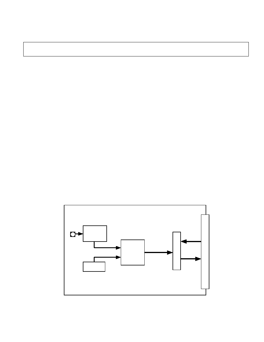
Evaluation Board 400kSPS, 14-Bit ADC
EVAL-AD7899CB
Fig. 1: FUNCTIONAL BLOCK DIAGRAM
FEATURES
Full-Featured Evaluation Board for the AD7899
Eval-Board Controller Compatible
Stand Alone Capability
On-Board Analog Buffering and Reference
Various Linking Options
PC Software for Control and Data Analysis when used
with Eval-Board Controller
I N T R O D U C T I O N
This Technical Note describes the evaluation board for the
AD7899 high speed, low power, 14-bit A/D converter that
operates from a single 5 V supply. Full data on the AD7899
is available in the AD7899 data sheet available from Analog
Devices and should be consulted in conjunction with this
Technical Note when using the Evaluation Board.
On-board components include an AD780 which is a +2.5V
ultra high precision bandgap reference and an op-amp for the
analog inputs. There are various link options which are
explained in detail on page 2.
Interfacing to this board is through a 96-way connector. This
96-way connector is compatible with the EVAL-BOARD
CONTROLLER which is also available from Analog De-
vices. External sockets are provided for the optional, exter-
nal,
CONVST and CLKIN and V
DRIVE
inputs and the
VIN1-VIN4 inputs.
OPERATING THE AD7899 EVALUATION BOARD
Power Supplies
When using this evaluation board with the EVAL-BOARD
CONTROLLER all supplies are provided from the EVAL-
BOARD CONTROLLER through the 96 way connector.
When using the board as a stand alone unit external supplies
must be provided. This evaluation board has seven power
supply inputs: V
DD
, A
GND
, +12V, -12V, A
GND
, V
DRIVE
and
D
GND
. If the evaluation board is used in stand-alone mode
+5V must be connected to the V
DD
input to supply the
AD7899 V
DD
pin and the AD780 voltage reference. +12V and
-12V are used to supply the op-amps. The V
DRIVE
pin can be
driven by a voltage between +3V and +5V allowing the
evaluation board to be connected to both +3V and +5V
systems. The supplies are decoupled to the relevant ground
plane with 10�F tantalum and 0.1�F multilayer ceramic
capacitors at the point where they enter the board. The supply
pins of all the op-amps and reference are also decoupled to
A
GND
with 10�F tantalum and a 0.1�F ceramic capacitor. The
AD7899 AV
DD
supply pin is decoupled to A
GND
with 47uF
tantalum and 0.1�F multilayer ceramic capacitors.
Extensive ground planes are used on this board to minimize
the effect of high frequency noise interference. There are two
ground planes, A
GND
and D
GND
. These are connected at one
location close to the AD7899.
A D7 899
A N A L O G
SIG N A L
C O N D IT IO N IN G
EX T ER N A L
R E F E R EN C E
DI
GI
TA
L
I/
O
BU
F
FE
RS
A N A L O G
IN P U T
96
W
AY
ED
GE
C
O
NN
EC
T
OR

EVAL-AD7899CB
� 2 �
REV. 0
Link and Switch Options
There are 9 link options which must be set for the required operating setup before using the evaluation board. The
functions of these options are outlined below.
Link No.
Function.
LK1
This link option selects the input range of the ADC. The position of this link is determined by the input
range required by the user. Please refer to the AD7899 data sheet for more information.
When this link is in position "A" V
INB
is connected to V
INA
.
When this link is in position "B" V
INB
is connected toAGND.
LK2
This link selects the reference source for the AD7899.
When a link is in position "A" the AD780 is selected as the reference source.
When a link is in position "B" an external voltage applied to SK7 is selected as the reference source.
When the link is removed completly the internal reference of the AD7899 is used as the reference source.
LK3
This link selects the source of the +12V supply.
When this link is in position "A" an external +12V must be connected to J2-1.
When this link is in position "B" the EVAL-BOARD CONTROLLER will provide the +12V supply
LK4
This link selects the source of the VDD supply.
When this link is in position "A" an external +5V must be connected to J2-2.
When this link is in position "B" the EVAL-BOARD CONTROLLER will provide the +5V supply
LK5
This link selects the source of the -12V supply.
When this link is in position "A" an external -12V must be connected to J2-4.
When this link is in position "B" the EVAL-BOARD CONTROLLER will provide the -12V supply
LK6
This link selects the source of the V
DRIVE
supply.
When this link is in position A the VDD supply is used as the V
DRIVE
supply.
When this link is in position B the DVDD supply of the EVAL-BOARD CONTROLLER is used as the
V
DRIVE
supply.
When this link is in position C an external supply on SK6 is used as the V
DRIVE
supply.
LK7
This link is used to select the source of the Conversion Start signal.
When this link is in position "A" the CONVST signal is generated by the EVAL-BOARD CONTROL-
LER.
When this link is in position "B" the CONVST signal is generated by an external signal connected to SK2.
LK8
This link selects the source of the CLKIN signal for the AD7899.
When this link is in position "A" the CLKIN signal is provided by the EVAL-BOARD CONTROLLER.
When this link is in position "B" the CLKIN signal can be provided by a signal applied to SK3. If no
signal is applied to SK3 the pin is pulled low and the internal oscillator is is used to control the conver-
sion.
LK9
This link sets the logic level of the STBY pin.
When a link is in position "A" the STBY pin is controlled by the FL1 flag pin of the EVAL-BOARD
C O N T R O L L E R .
When a link is in position "B" the STBY pin is tied to VDD and the part is in normal operating mode.
When a link is in position "C" the STBY pin is tied to DGND and the part is in standby mode.

EVAL-AD7899CB
REV. 0
� 3 �
SET-UP CONDITIONS
Care should be taken before applying power and signals to the evaluation board to ensure that all link positions are as
per the required operating mode. Table I shows the position in which all the links are set when the evaluation board is
shipped. The board is compatible with the EVAL-BOARD CONTROLLER when shipped.
Table I. Initial Link and Switch Positions
Link No.
Position
Function.
LK1
B
The largest voltage range for the part is selected.
LK2
A
The AD780 is selected as the reference source for the AD7899.
LK3-5
B
The EVAL-BOARD CONTROLLER is used to provide the supply voltages for the
evaluation board.
LK6
A
The V
DRIVE
pin is connected to the VDD supply.
LK7
B
The CONVST signal is provided by the EVAL-BOARD CONTROLLER.
LK8
B
The CLKIN can be supplied either by an external signal connected to SK3 or by the
AD7899s internal oscillator.
LK9
B
The STBY pin is tied to VDD

EVAL-AD7899CB
� 4 �
REV. 0
EVALUATION BOARD INTERFACING
Interfacing to the evaluation board is via a 96-way connector,
J1. J1 is used to connect the evaluation board to the EVAL-
BOARD CONTROLLER or other system. The pinout for
the J1 connector is shown in Figure 2 and its pin designations
are given in Table II.
1
32
1
32
A
B
C
Fig. 2. Pin Configuration for the 96-Way Connector, J1
96-Way Connector Pin Description
F L 1
Flag one. This is a logic input and is connected
to the
STBY pin of the AD7899. A logic high on
this pin allows normal operation of the AD7899.
A logic low on this pin puts the AD7899 into
standby mode.
D0-D13
Data Bit 0 to Data Bit 13. Bi-directional data
pins. These data bits provide the ADC conversion
results during a read operation.
R D
Read. This is an active low logic input which is
used in conjunction with the
CS pin to enable the
data outputs.
W R
Write. A logic input. A rising edge on this input,
with CS low and RD high latches the logic state
on D0-D3 into the channel select register. Soft-
ware selection of channels is not supported by this
evaluation board.
C S
Chip Select. An active low logic input. A low
level on this input selects the AD7899.
F L 0
Flag zero. This logic input is connected to the
CONVST input of the AD7899 via LK7. A low
to high transition on this input puts all the track/
holds into their hold mode and starts conversion
on the selected channels. In addition the state of
the channel sequence selection is also latched on
the rising edge of this input
IRQ2
Interrupt Request 2. This is a logic output and is
connected to the BUSY logic output on the
AD7899. This output will go high on the rising
edge of
CONVST and will return low when
conversion is completed on all selected channels.
D G N D
Digital Ground. These lines are connected to the
digital ground plane on the evaluation board. It
allows the user to provide the digital supply via
the connector along with the other digital signals.
A G N D
Analog Ground. These lines are connected to the
analog ground plane on the evaluation board.
AV
DD
Analog +5V Supply. These lines are connected to
the V
DD
supply line on the board via LK4.
+12V
+12V Supply. This line is connected to the +12V
supply line on the board via LK3.
-12V
-12V Supply. This line is connected to the -12V
supply line on the board via LK5.
Table II. 96-Way Connector Pin Functions.
ROW a
RowB
RowC
1
F L 1
2
D 0
3
SCLK1
D 1
SCLK1
4
D G N D
D G N D
D G N D
5
D 2
6
D 3
7
D 4
8
9
R D
D 5
W R
10
D 6
C S
11
D 7
12
D G N D
D G N D
D G N D
13
D 8
14
D 9
15
D10
16
D G N D
D G N D
D G N D
17
F L 0
D11
IRQ2
18
D12
D13
19
20
D G N D
D G N D
D G N D
21
A G N D
A G N D
A G N D
22
A G N D
A G N D
A G N D
23
A G N D
A G N D
A G N D
24
A G N D
A G N D
A G N D
25
A G N D
A G N D
A G N D
26
A G N D
A G N D
A G N D
27
A G N D
28
A G N D
29
A G N D
A G N D
A G N D
30
-12V
A G N D
+12V
31
32
AVDD
AVDD
AVDD
Note : The unused pins of the 96-way connector are not shown.

EVAL-AD7899CB
REV. 0
� 5 �
S O C K E T S
There are six input sockets relevant to the operation of the
AD7899 on this evaluation board. The function of these
sockets is outlined in Table III.
Table III. Socket Functions
Socket
Function
SK1
Sub-Miniature BNC Socket for the analog
input.
SK2
Sub-Miniature BNC Socket for the exter-
nal reference
SK3
Sub-Miniature BNC Socket for external
V
DRIVE
supply.
SK4
Sub-Miniature BNC Socket for BUSY
output.
SK5
Sub-Miniature BNC Socket for external
CONVST input.
SK6
Sub-Miniature BNC Socket for the exter-
nal CLKIN input.
C O N N E C T O R S
There are two connectors on the AD7899 evaluation board
as outlined in Table IV.
Table IV. Connector Functions
Connector
Function
J 1
96-Way Connector for Parallel Interface con-
nections.
J 2
External +12V, -12V +5V & A
GND
power
connector.
OPERATING WITH THE EVAL-BOARD
CONTROLLER
The evaluation board can be operated in a stand-alone mode
or operated in conjunction with the EVAL-BOARD CON-
TROLLER. The EVAL-BOARD CONTROLLER is avail-
able from Analog Devices under the order entry
"EVAL-BOARD CONTROLLER". When operated with
this control board, all supplies and control signals to operate
the AD7899 are provided by the EVAL-BOARD CON-
TROLLER. Software to communicate with the Control
Board and AD7899 is provided with the AD7899 evaluation
board package. This EVAL-BOARD CONTROLLER will
also operate with all Analog Devices evaluation boards which
end with the letters CB in their title.
The 96-way connector on the EVAL-AD7899CB plugs
directly into the 96-way connector on the EVAL-BOARD
CONTROLLER. The EVAL-BOARD CONTROLLER
provides all the supplies for the evaluation board. Itis
powered from a 12VAV transformer. Suitable transformers
are available from Analog Devices as an accessory under the
following part numbers:
EVAL-110VAC-US:
For use in the U.S. or Japan
EVAL-220VAC-UK:
For use in the U.K.
EVAL-220VAC-EU:
For use in Europe
These transformers are also available for other suppliers
including Digikey (U.S.) and Campbell Collins (U.K.).
Connection between the EVAL-BOARD CONTROLLER
and the serial port of a PC is via a standard Centronics printer
port cable which is provided as part the EVAL-BOARD
CONTROLLER package. Please refer to the manual which
accompanies the EVAL-BOARD CONTROLLER for more
details on the EVAL-BOARD CONTROLLER package.